Drawing structure for bearing oil seals for building material lifting machine

A bearing oil seal and mechanical technology, which is applied in the field of external pulling device for bearing oil seals of building materials hoisting equipment, can solve the problems of low oil seal efficiency and heavy workload, and achieve the effects of improving work efficiency, improving applicability, and compact overall structure

Inactive Publication Date: 2018-01-12
付云杰
View PDF0 Cites 0 Cited by
  • Summary
  • Abstract
  • Description
  • Claims
  • Application Information

AI Technical Summary

Problems solved by technology

Aiming at the low efficiency and heavy workload of manually pulling out the oil seal in the prior art, the present invention designs a tool that can simplify the manual operation so as to improve the pulling out efficiency; Cut out the unloading groove, then place the U-shaped groove of the supporting base on the end face of the bearing, and move the pull-out rod in the hollow adjustment cylinder according to the distance between the unloading groove and the bottom of the U-shaped groove, so that the pull-out rod The clamping disc at the end directly contacts the inner wall of the oil seal through the withdrawal groove, and then the pull-out rod is fixed in the adjusting cylinder through the thread fit between the external thread and the inner wall of the adjusting cylinder, and then the manual use of a wrench or other pneumatic equipment is used to start the adjustment. The screw nut on the adjustment cylinder rotates, so that the adjustment cylinder and the pull-out rod move upwards in the through hole until the oil seal is completely pulled out; the overall structure of the invention is compact, and the disassembly and connection between the components can be realized, which is convenient for manual use , and for different types of bearings, the position of the pull-out rod can be adjusted. Even if the distance between the side wall of the oil seal of each bearing and the bottom of the U-shaped groove is different, the pull-out rod can still accurately pass through the withdrawal groove and the oil seal. contact with the inner wall of the inner wall, which greatly improves the applicability of the present invention; the abdication hole connected with the through hole meets the requirements, and the diameter of the abdication hole is larger than the outer diameter of the adjustment cylinder. When the oil seal is completely pulled out, the adjustment cylinder slides along the inner wall of the abdication hole until The adjustment cylinder is completely moved out of the U-shaped groove to complete the separation of the support base from the adjustment cylinder and the pull-out rod, which is convenient for storage

Method used


Image

  • Drawing structure for bearing oil seals for building material lifting machine
  • Drawing structure for bearing oil seals for building material lifting machine
  • Drawing structure for bearing oil seals for building material lifting machine

Examples


Embodiment 1

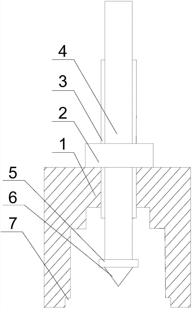
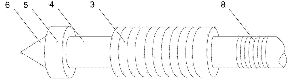
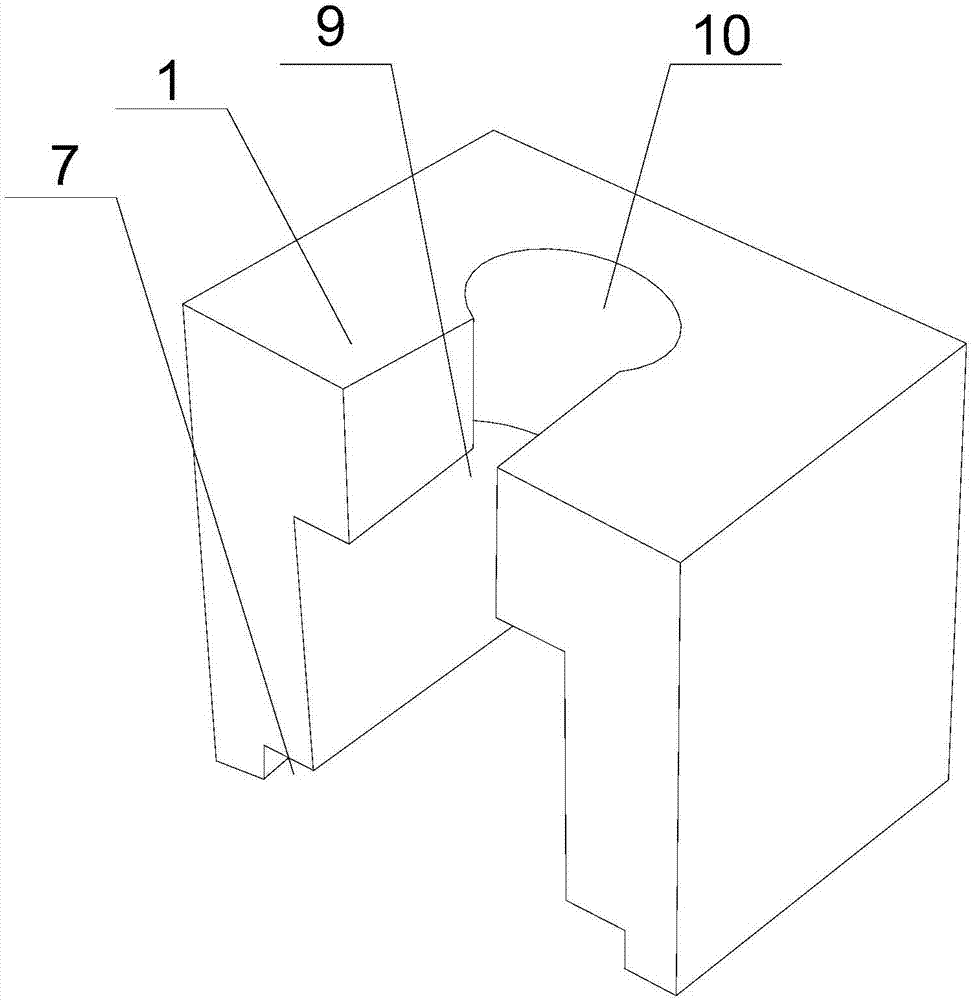
[0020] Such as Figure 1 to Figure 3 As shown, this embodiment includes a support base 1 with a U-shaped groove at the bottom, a through hole 10 and an abdication hole 9 communicating with each other are opened at the upper end of the support base 1, and the extraction rod 4 passes through the through hole 10 and is placed in a U-shaped In the groove, a hollow adjustment cylinder 3 is set in the middle of the extraction rod 4, the adjustment cylinder 3 is in contact with the inner wall of the through hole 10, and an external thread 8 is also provided on the outer wall of the extraction rod 4, and the The external thread 8 is threadedly matched with the upper part of the inner wall of the adjustment cylinder 3, and the end of the extraction rod 4 is equipped with a snap-in disc 5, and the outer diameter of the snap-in disc 5 is larger than the outer diameter of the extraction rod 4; it also includes a screw nut 2, The screw nut 2 is threadedly matched with the adjustment cylind...


PUM


Abstract

The invention discloses a drawing structure for bearing oil seals for a building material lifting machine. The drawing structure comprises a supporting base, and further comprises a nut, wherein a U-shaped groove is formed in the bottom of the supporting base; a through hole and a receding hole are formed in the upper end of the supporting base; a pull-out rod penetrates through the through hole to be arranged in the U-shaped groove; a hollow adjusting cylinder is arranged in the middle of the pull-out rod in a sleeving mode and makes contact with the inner wall of the through hole; external threads are further arranged on the outer wall of the pull-out rod and are in threaded fit with the upper section of the inner wall of the adjusting cylinder; a clamping disc is arranged at the tail end of the pull-out rod; the outer diameter of the clamping disc is larger than the outer diameter of the pull-out rod; and the nut is in threaded fit with the adjusting cylinder. According to the drawing structure, detachable connection between all parts can be realized, manual use can be facilitated, in addition, the position of the pull-out rod can be adjusted according to different types of bearings, even if the distances between the side walls of the oil seals of the bearings and the bottom of the U-shaped groove are different, the pull-out rod can still accurately penetrate through stripping grooves to make contact with the inner walls of the oil seals, and therefore the applicability of the drawing structure can be improved.

Description

technical field [0001] The invention relates to the field of building construction, in particular to an external pulling device for bearing oil seals of building material hoisting equipment. Background technique [0002] In the process of high-rise building construction, a large number of building materials need to be hoisted from the ground to the high-rise floor, such as channel steel, pipe fittings or other special-shaped metal connectors; Stable operation requires timely and regular inspection and replacement of LL-type oil seals. During the replacement process of LL-type oil seals, the temporarily sealed oil seal removal groove is usually opened, and then the oil seal is pulled out of the bearing with tools such as pliers. Because LL-type The press-fitting of the oil seal is realized by a hydraulic press-fitting mold, so the oil seal is closely attached to the bearing, and manual operation requires a large amount of labor, increases the workload of workers, and is ineff...

Claims


Application Information

Patent Timeline
Patent Type & Authority Applications(China)
IPC IPC(8): B25B27/00
Inventor 付云杰
Owner 付云杰
Why Eureka
Try Eureka