
Hydro jets for pitch ball replacement nozzles

A technology of hydraulic injector and nozzle, which is applied in wellbore/well components, production fluid, earthwork drilling and production, etc. It can solve the problems of severe nozzle erosion, increase the difficulty of construction, deformation of internal flow channel, etc., and achieve good sealing effect , cost saving, and stable structure

Active Publication Date: 2019-05-28
YANSHAN UNIV
View PDF6 Cites 0 Cited by
  • Summary
  • Abstract
  • Description
  • Claims
  • Application Information

AI Technical Summary

Problems solved by technology

[0004] (1) Abrasives (quartz sand, etc.), fracturing fluid and proppant used in sandblasting and perforation all need to pass through the nozzle and be pumped into formations and fractures at high pressure and displacement, resulting in severe nozzle erosion, The deformation of the internal flow channel affects the smooth progress of fracturing construction. Since the nozzles of the existing hydraulic injectors are fixed nozzles, when the nozzles are damaged, the pipe string needs to be lifted in time to replace the damaged nozzles on the ground;
[0005] (2) For different sections of a pipe string fracturing, the construction parameters are different, and different nozzle combinations are required. The nozzles of the existing hydraulic jets can only be replaced on the ground, and the pipe string must be lifted, resulting in time and cost. and waste of human resources, especially for complex underground conditions, which increases the difficulty of construction

Method used


Image

  • Hydro jets for pitch ball replacement nozzles
  • Hydro jets for pitch ball replacement nozzles
  • Hydro jets for pitch ball replacement nozzles

Examples


Embodiment Construction

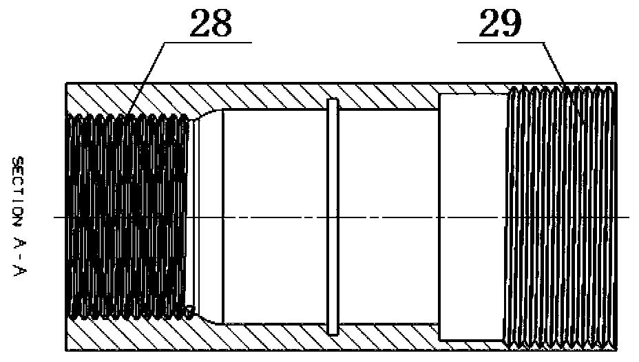
[0037] exist figure 1 In the shown schematic diagram of the water power injector for replacing the nozzle with a ball, the outer cylinder with a cavity is set outside the inner cylinder 1 with a cavity, and the elastic ball seat 8 is set in the inner cylinder through a pin 9 and is fixedly connected with the inner cylinder, as shown in Figure 10 As shown, the large end of the horn plate 81 with cracks in the elastic ball seat is fixed with a fixed plate 83 extending along the direction of the small end of the horn plate and can be fixed with the inner cylinder by pins. The fixed plate 83 is provided with several The through holes of the fixed plate are transparent, and the speaker plate 81 is provided with a plurality of transparent through holes 82 at intervals.

[0038] Such as figure 2 As shown, the second outer cylinder 6 in the outer cylinder is threadedly connected with the first outer cylinder 2; image 3 As shown, one end of the first outer cylinder is a female joi...


PUM


Abstract

The invention discloses a hydraulic ejector for replacing a nozzle by casting a ball. The hydraulic ejector comprises an inner cylinder, an outer cylinder, a spring, a rotatable sliding sleeve and anelastic ball seat; the outer cylinder is arranged out of the inner cylinder in a sleeving mode, the spring and the rotatable sliding sleeve are arranged between the inner cylinder and the outer cylinder, and the elastic ball seat which is arranged in the inner cylinder is close to a pin end and fixedly connected with the inner cylinder through a pin nail and capable of pressurizing the fluid; theouter cylinder comprises a first outer cylinder and a second outer cylinder, wherein the second outer cylinder is located at the end part of the first outer cylinder and is in threaded connection withthe first outer cylinder; the inner cylinder comprises two parts with unequal wall thicknesses, and intersecting edge parts of the unequal thickness part of the inner cylinder are four evenly-distributed right-angle transitioned serrated pressing blocks with points; and four protruding sliding blocks are evenly distributed at one end of the inner cylinder with a thick wall. The hydraulic ejectorfor replacing the nozzle by casting the ball is simple in structure, the process is easy to control, the fact that automatic switching of a spraying nozzle can be realized without landing a pipe column of the hydraulic ejector is realized by controlling the pressure of the fluid, the ejector is steady in structure, stable in running, and cost, time and a lot of human resources are saved. The hydraulic ejector for replacing the nozzle by casting the ball is applied to hydraulic jet fracturing in the development process of oil and gas fields.

Description

technical field [0001] The invention belongs to the field of petroleum and natural gas engineering, in particular to a hydraulic injector. Background technique [0002] At present, in the process of oil and gas field development, the production of new wells, stable production of old wells, and measures to increase oil production all rely on conventional stimulation measures such as fracturing and acidification to varying degrees. Hydraulic jet fracturing is a combination of perforating, fracturing, and isolation The new stimulation technology is suitable for the stimulation of vertical wells and horizontal wells in low permeability reservoirs, and is an effective method for fracturing stimulation of low permeability reservoirs. [0003] Hydraulic jet fracturing can perform perforation and fracturing at designated locations, and can realize fracturing of multiple intervals in one string without mechanical isolation. The ejector plays the role of perforation in the hydraulic ...

Claims


Application Information

Patent Timeline
Patent Type & Authority Patents(China)
IPC IPC(8): E21B43/114E21B43/26
Inventor 李子丰张超越任文明
Owner YANSHAN UNIV
Learn More