Advanced forecasting emission and measurement device in underground engineering chromatofocusing induced polarization method

A technology of induced polarization and focused tomography, which is applied in measuring devices, geophysical surveying, radio wave measuring systems, etc., can solve problems affecting construction, large section of working face, inconvenient installation of electrodes and connecting cables, etc., and achieves improvement Work efficiency, avoid insulation protection, improve the effect of power supply

Active Publication Date: 2013-05-15
山东百廿慧通工程科技有限公司
View PDF4 Cites 10 Cited by
  • Summary
  • Abstract
  • Description
  • Claims
  • Application Information

AI Technical Summary

Problems solved by technology

When the focused tomography induced polarization method works, it is necessary to drill holes around the working surface and arrange a number of shielding electrodes, and to arrange a large number (20-40) of measuring electrodes on the working surface. It is time-consuming to drill so many electrode holes. During the measurement, the electrodes on the working surface should not only serve as power supply electrodes to supply power to the working surface, but also serve as receiving electrodes to receive voltage signals from the working surface. It is necessary to arrange two electrodes at one electrode position, one copper electrode as The power supply electrode, one is a non-polarized electrode as the receiving electrode, which doubles the number of electrode holes and electrodes, and the general working surface has a large cross-section. It is extremely inconvenient to install electrodes and connect cables. It is difficult to operate with the help of a loading vehicle, and the risk factor is higher. Large and individual positions cannot be completed; and the measurement of the electrodes needs to be manually operated, which is inconvenient to operate and low in work efficiency

Method used


Image

  • Advanced forecasting emission and measurement device in underground engineering chromatofocusing induced polarization method
  • Advanced forecasting emission and measurement device in underground engineering chromatofocusing induced polarization method
  • Advanced forecasting emission and measurement device in underground engineering chromatofocusing induced polarization method

Examples


Embodiment Construction

[0030] The present invention will be further described below in conjunction with the accompanying drawings and embodiments.

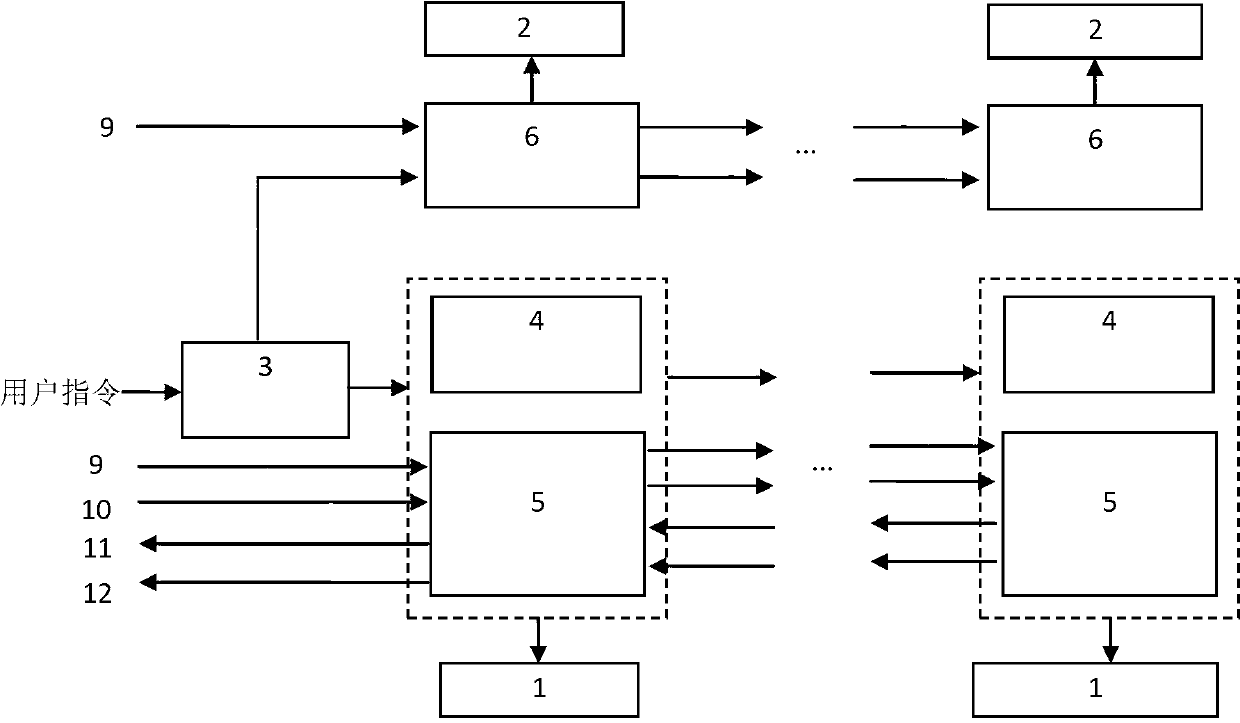
[0031] Such as figure 1 As shown, a focused tomography induced polarization method for underground engineering forecasting emission and measurement device mainly includes: intelligent electrode 1, self-adsorption shielding electrode 2, automatic electrode control device, and electrode guide rail. The smart electrode 1 is fixed on the working surface through the electrode guide rail, and the self-adsorption shielding electrode 2 is arranged around the working surface to emit shielding current. Under the control of the electrode automatic control device, the switching of the transmitting or receiving function of the smart electrode 1 is controlled and controlled. The smart electrode 1 realizes the automatic switching of the electrode sequence according to the user-defined instructions, thereby realizing the automatic transmission and reception function of...


PUM


Abstract

The invention relates to an advanced forecasting emission and measurement device in an underground engineering chromatofocusing induced polarization method. The advanced forecasting emission and measurement device structurally comprises an intelligent electrode, a shielding electrode and an electrode automatic control device. The electrode automatic control device comprises a decoder, an intelligent electrode switching circuit, an intelligent electrode switch circuit and a shielding electrode switch circuit. According to the advanced forecasting emission and measurement device, automatic switching between the emission function and the receiving function of the intelligent electrode is realized, and the intelligent electrode is controlled to realize automatic switching of electrode arrays according instructions defined by a user. Moreover, the number of shielding electrodes can be controlled so that the emission and receiving functions which are in high automation degree in the chromatofocusing induced polarization method are realized.

Description

technical field [0001] The invention relates to a focused tomography induced polarization advanced forecasting device in underground engineering such as tunnels or tunnels, in particular to an underground engineering focused tomographic induced polarization advanced forecast emission and measurement device. Background technique [0002] As an important electromagnetic prospecting method, induced polarization method is widely used in resource prospecting and engineering prospecting because of its unique advantages (economical, non-destructive, fast and rich in information, etc.). The induced polarization method achieves the purpose of detection and prediction by receiving and analyzing the induced polarization effects of various abnormal bodies. It has the characteristics of being sensitive to the bad water body of the tunnel, and can be used to predict the abnormal water inrush in front of the working face, especially the water inrush in front of the tunnel. In the advanced...

Claims


Application Information

Patent Timeline
Patent Type & Authority Applications(China)
IPC IPC(8): G01V3/02
Inventor 聂利超刘斌李术才宋杰刘征宇林春金徐磊许新骥王传武郝亭宇周浩牛健张孝健
Owner 山东百廿慧通工程科技有限公司
Why Eureka
Try Eureka