Automatic clutch type direct-current brushless motor stator

A brushless DC motor, automatic clutch technology, applied in the direction of electric components, electrical components, electromechanical devices, etc., can solve the problems of small adaptability, poor climbing ability and overload ability, large output torque, etc., to achieve simple and compact structure, The effect of improving gradeability and large transmission torque

Inactive Publication Date: 2012-10-03
马加良
View PDF6 Cites 11 Cited by
  • Summary
  • Abstract
  • Description
  • Claims
  • Application Information

AI Technical Summary

Problems solved by technology

This mode is simple in structure and easy to control, but in actual use, electric vehicles have different requirements for different road conditions; when driving normally, the brushless DC motor is required to have a fast speed and a small output torque; Or when the load is heavy, the brushless DC motor is required to have a slow speed and a large output torque; its shortcomings are: First, because the motor is designed according to normal operating conditions, the output torque cannot be changed under the condition of constant motor power. Therefore, When starting, climbing and heavy loads, the motor is often operated in an abnormal state, forcing the motor to work in a low-efficiency area, causing the motor to stall, heat up, or even stop rotating, causing shocks to important components such as the motor, battery, and controller. , shorten the life; the second is poor climbing ability and overload ability, small adaptability, low operating efficiency, and short mileage
For this reason, many manufacturers and people of insight have carried out fruitful development and research, but no reasonable products have come out so far.

Method used


Image

  • Automatic clutch type direct-current brushless motor stator
  • Automatic clutch type direct-current brushless motor stator

Examples


Embodiment Construction

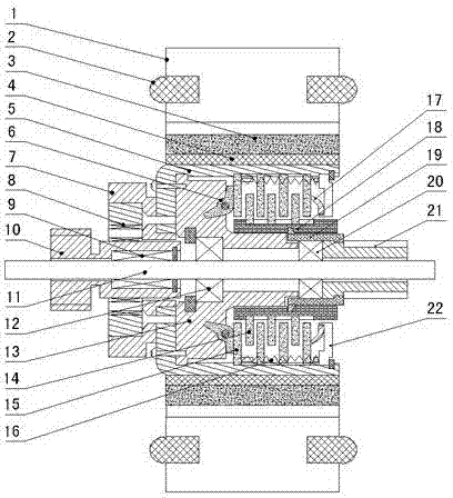
[0012] figure 1 As shown, the invention creates a specific embodiment of the automatic clutch type brushless DC motor rotor, which includes a main shaft 11, an automatic clutch, a rotor magnetic steel 3, and a magnetic isolation sleeve 4. The automatic clutch is rotatably installed on the main shaft 11 Above, the magnetic isolation sleeve 4 is fixed on the outer casing 5 of the automatic clutch, and the rotor magnets 3 are evenly distributed on the magnetic isolation sleeve 4; A one-way device 8 is fixed on the seat 7 , and the low-speed central gear 10 is rotatably arranged on the main shaft 11 through the first bearing 9 , and the inner ring of the one-way device 8 cooperates with the low-speed central gear 10 .

[0013] The automatic clutch includes an outer casing 5, a counterweight fixing seat 13, a centrifugal block 6, an outer friction plate 15, an inner friction plate 14, a bowl-shaped elastic washer 17, an outer ring sleeve 18, an inner ring sleeve 19 and a cover plat...


PUM


Abstract

The invention discloses an automatic clutch type direct-current brushless motor stator which comprises a main shaft (11), an automatic clutch, rotor magnetic steel (3) and a magnetic separation sleeve (4), wherein the automatic clutch is arranged on the main shaft (11) in a rotating way, the magnetic separation sleeve (4) is fixed on a shell (5) of the automatic clutch, the rotor magnetic steel (3) is uniformly distributed on the magnetic separation sleeve (4), an isolator seat (7) is fixedly arranged on the end surface of the shell (5) of the automatic clutch, an isolator (8) is fixedly arranged on the isolator seat (7), a low-speed central gear (10) is arranged on the main shaft (11) in the rotating way, an inner ring of the isolator (8) is matched with the low-speed central gear (10), and a high-speed central gear (21) which is matched with the automatic clutch is arranged on the main shaft (11). By adopting the structure, the automatic clutch type direct-current brushless motor stator has the advantages of being simple and compact in structure, small in volume, large in transmission torsion, low in accuracy requirement, long in service life, and good in university and having the capability of automatic transmission and the like.

Description

technical field [0001] The invention relates to a DC brushless motor rotor, in particular to an automatic clutch type DC brushless motor rotor capable of outputting different speeds according to changes in rotational speed. Background technique [0002] Electric vehicles are popular among consumers due to their energy saving and environmental protection, simple operation, convenient use, and low operating costs. At the same time, they have also received great attention from governments at all levels. Electric vehicles have entered a rapid development channel, and hub motors are in short supply. [0003] At present, the wheel hub motors used in electric vehicles generally adopt DC brushless motors, and the wheel hubs are driven to rotate through the DC brushless motors to achieve the purpose of riding electric vehicles. This mode is simple in structure and easy to control, but in actual use, electric vehicles have different requirements for different road conditions; when dri...

Claims


Application Information

Patent Timeline
Patent Type & Authority Applications(China)
IPC IPC(8): H02K1/22H02K7/108
Inventor 马加良邱亚平沈毓庆邱达平
Owner 马加良
Why Eureka
Try Eureka