

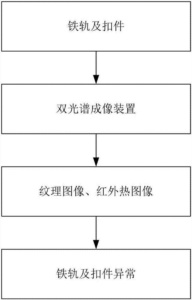
Method for detecting abnormal conditions of rails and fasteners through double-spectrum imaging
An anomaly detection and dual-spectrum technology, applied to railway car body components, optical testing flaws/defects, railway vehicle shape measuring devices, etc., can solve problems such as loose rails and fasteners
- Summary
- Abstract
- Description
- Claims
- Application Information
AI Technical Summary
Problems solved by technology
Method used
Image

Examples
Embodiment 1
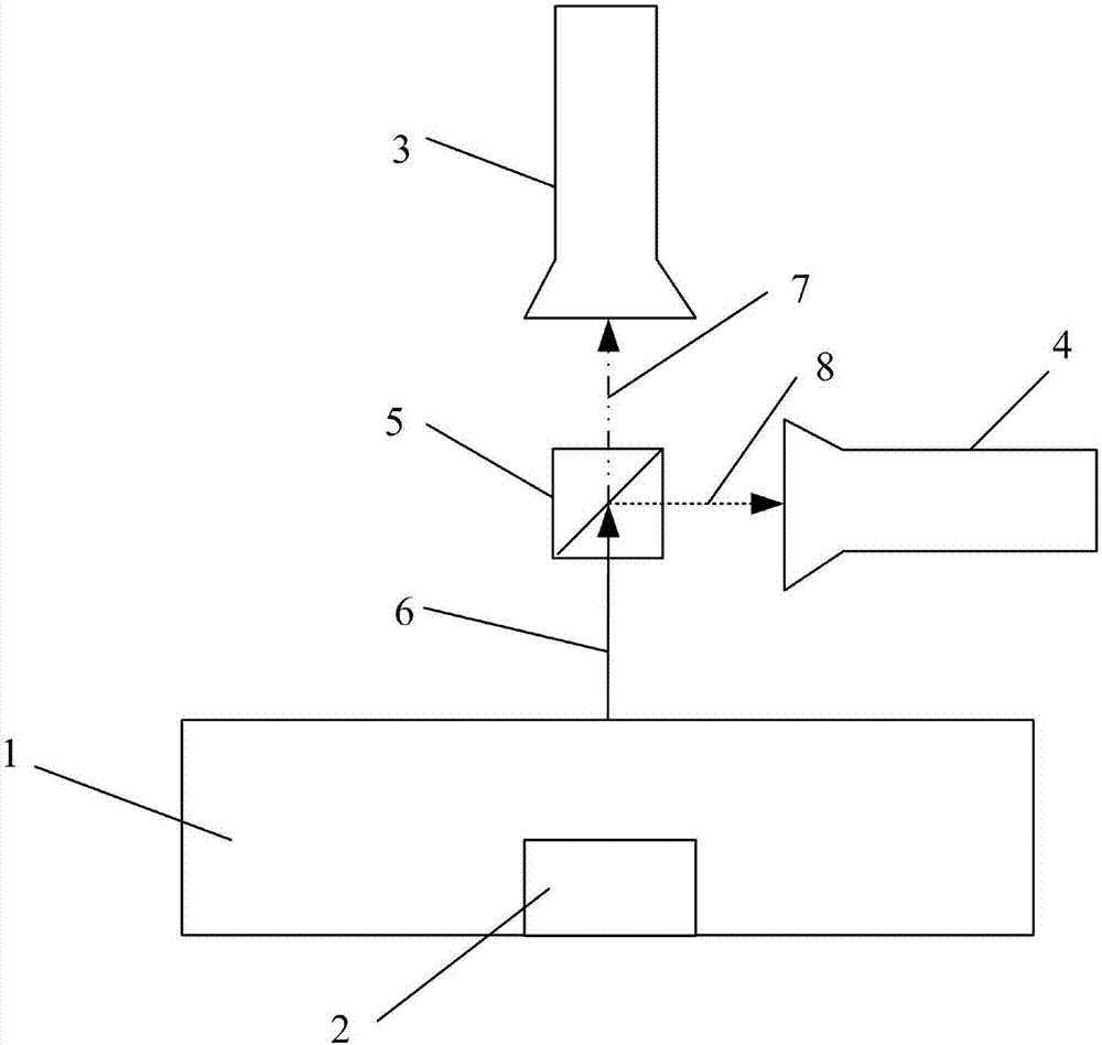
[0074] Such as figure 2As shown, a visible light area array camera 3 and an infrared area array camera 4 are used to form a dual-spectrum area array imaging device 11, wherein the optical axis of the visible light area array camera 3 and the infrared area array camera 4 are perpendicular to each other. A dichroic mirror 5 is arranged on the optical axis of the camera, and the light splitting surface of the dichroic mirror 5 forms an angle of 45 degrees with the optical axes of the visible light array camera 3 and the infrared array camera 4; Visible, near-infrared and mid-to-far infrared mixed light 6 is separated into visible light and near-infrared mixed light 7 and mid-to-far infrared light 8, which respectively enter the visible light area array camera 3 and infrared camera 4 to obtain dual-spectrum images; adjust the visible light area array camera 3 , the distance and the angle from the infrared area array camera 4 to the dichroic mirror 5 splitting surfaces, so that th...
Embodiment 2
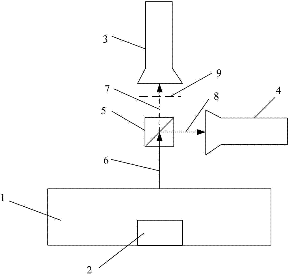
[0076] The difference from Embodiment 1 is that an illumination light source is provided beside the dual-spectrum area array imaging device 11, and the light source is projected onto the rail 1 and fastener 2 areas, and the wavelength of the light source is 800nm, such as image 3 As shown, an 800nm narrow-band filter 9 is set at the front end of the visible light camera to eliminate ambient light interference and obtain surface texture images of rails and fasteners with consistent brightness.
Embodiment 3
[0078] The difference from Example 2 is that, as Figure 4 As shown, three parallel light surface light sources 10 are arranged next to the dual-spectrum area array imaging device 11, of which two parallel light surface light sources 10-1 and 10-2 are located directly above the area of the fastener 2 on both sides of the rail, and one parallel light source The surface light source 10-3 is obliquely incident on the rail 1, the angle between the incident direction and the longitudinal direction of the rail 1 is 20 degrees, and the irradiation areas of the three light sources do not overlap.
[0079] Such as Figure 5 As shown, when the parallel surface light source 10-3 is obliquely incident on the rail 1, a dark field lighting system is formed between the visible light area array camera 3; After the parallel light reaches the surface of the rail, most of the light energy is emitted in the form of mirror reflection, and cannot enter the visible light area array camera 3, so t...
PUM
 Abstract
Description
Claims
Application Information