Welding type cable conductor connector having current sharing effect and welding method

A technology for welding joints and cable conductors, which is applied in welding/welding connections, circuits, connections, etc. It can solve the problems of reducing the skin effect of conductors, not considering the connection problems of cable intermediate joints and cable outlet conductors, etc., to improve the current The effect of distribution uniformity, reducing line operation loss, and improving transmission efficiency

Active Publication Date: 2018-01-12
STATE GRID CORP OF CHINA +3
View PDF9 Cites 2 Cited by
  • Summary
  • Abstract
  • Description
  • Claims
  • Application Information

AI Technical Summary

Problems solved by technology

The existing large-section enameled wire layered insulated conductor adopts the technology of layered stranding of enameled wire and bare copper conductor, which can reduce the skin effect of

Method used


Image

  • Welding type cable conductor connector having current sharing effect and welding method
  • Welding type cable conductor connector having current sharing effect and welding method
  • Welding type cable conductor connector having current sharing effect and welding method

Examples


Embodiment 1

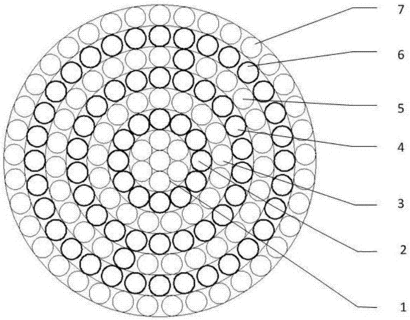
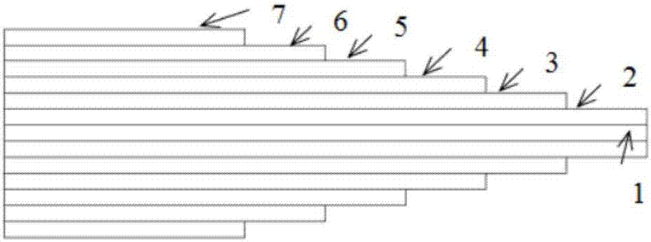
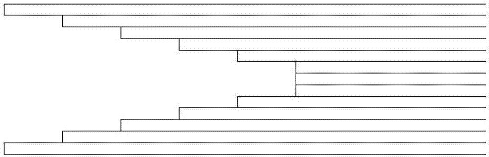
[0033] The total number of layers of the conductor is 7 layers, and the conductor is divided into two parts for welding. The inner welding layer is 5 layers and the outer welding layer is 2 layers. Before welding starts, use a pipe cutter to make the male head of the welded joint. The outer layer of the conductor monofilament is 15mm shorter than the adjacent inner layer, and the two layers in the center are sawed flush. eventually into a ladder figure 2 As shown, and fasten each layer tightly. Use low-resistivity electrode A when welding the inner 5-layer conductor, and use high-resistivity electrode B when welding the outer 2-layer conductor. The production of the female head of the welded joint is carried out in conjunction with the male head. First, use a pipe cutter to cut the conductor on each layer. The outer layer of the conductor monofilament is 15mm longer than the adjacent inner layer, and the two layers in the center are sawed evenly. image 3 , use low-resistiv...

Embodiment 2

[0036] The total number of layers of the conductor is 7 layers, and the conductor is divided into two parts for welding. The inner welding layer is 5 layers and the outer welding layer is 2 layers. Before welding starts, use a pipe cutter to make the male head of the welded joint. The outer layer of the conductor monofilament is 20mm shorter than the adjacent inner layer, and the two layers in the center are sawed flush. eventually into a ladder figure 2 As shown, and fasten each layer tightly. Use low-resistivity electrode A when welding the inner 5-layer conductor, and use high-resistivity electrode B when welding the outer 2-layer conductor. The production of the female head of the welded joint is carried out in conjunction with the male head. First, use a pipe cutter to cut the conductor on each layer. The outer layer of the conductor monofilament is 20mm longer than the adjacent inner layer, and the two layers in the center are sawed evenly. image 3 , Before welding, ...


PUM


Abstract

The invention belongs to the power transmission line power cable field and particularly relates to a welding type cable conductor connector having the current sharing effect and a welding method. Thetotal layer quantity of conductors is N, when M layers of internal conductors are welded, low resistivity welding rods A are utilized, when O layers of middle conductors are welded, low resistivity welding rods A are utilized, when (N-M-O) layers of external conductors are welded, high resistivity welding rods B are utilized. The method is advantaged in that a problem of temperature rising of theconductors and connector points during application of large-cross section layered insulation conductors can be solved. On the condition that the layered energy saving and consumption reduction conductor performs the effective AC resistance reduction effect, disadvantages of relatively large AC resistance and relatively high temperature existing in a traditional crimping type cable conductor connector under long-term rated work conditions are ameliorated, the process is simple, field maneuverability is strong, line operation loss of the large-cross section AC power cable can be reduced, power transmission efficiency is improved, and the excellent energy saving and consumption reduction effect is realized.

Description

technical field [0001] The invention belongs to the field of power transmission lines and power cables, and in particular relates to a welded cable conductor joint with a current equalizing function and a welding method. Background technique [0002] The skin effect, also known as the skin effect, refers to a phenomenon that when an alternating current passes through a conductor, the current distribution on the cross-section of the conductor is uneven due to induction, and the closer to the surface of the conductor, the greater the current density. This phenomenon is called "skin effect". The skin effect increases the effective resistance of the conductor. When the low-frequency current flows through a thin wire, the skin effect can be ignored, but the higher the frequency and the larger the conductor cross-section, the skin effect cannot be ignored. Especially at 800mm 2 The skin effect in the above-mentioned large cross-section cable conductor is the main reason why the ...

Claims


Application Information

Patent Timeline
IPC IPC(8): H01R4/02H01R43/02H01R43/28
Inventor 江贞星杨黎明朱智恩马一力胡列翔郑海王少华
Owner STATE GRID CORP OF CHINA
Why Eureka
Try Eureka