Crimping type cable conductor connector with current sharing effect and preparation method

A cable conductor, crimping technology, applied in the field of power cables and transmission lines, can solve the problems of hidden safety hazards at the joints of the cable conductors, high temperature rise at the joints, etc., to improve the uniformity of current distribution and improve the AC resistance. , The effect of reducing the AC resistance

Active Publication Date: 2018-01-19
STATE GRID CORP OF CHINA +3
View PDF9 Cites 2 Cited by
  • Summary
  • Abstract
  • Description
  • Claims
  • Application Information

AI Technical Summary

Problems solved by technology

[0005] In the existing crimping type conductor joint, the cable conductor in the crimping part is not specially treated. When the current flows from one side of the conductor into the other side of the conductor, it must flow into the inner side of the conductor from the contact surface of the conductor and the connecting pipe. When it is large, due to the skin effect, the current density inside the conductor is smaller than that outside the conductor, so that in the long-term operation of the cable under the rated current carrying capacity, a high temperature rise will occur at the joint, making the cable conductor joint a potential safety hazard

Method used


Image

  • Crimping type cable conductor connector with current sharing effect and preparation method
  • Crimping type cable conductor connector with current sharing effect and preparation method
  • Crimping type cable conductor connector with current sharing effect and preparation method

Examples


Embodiment 1

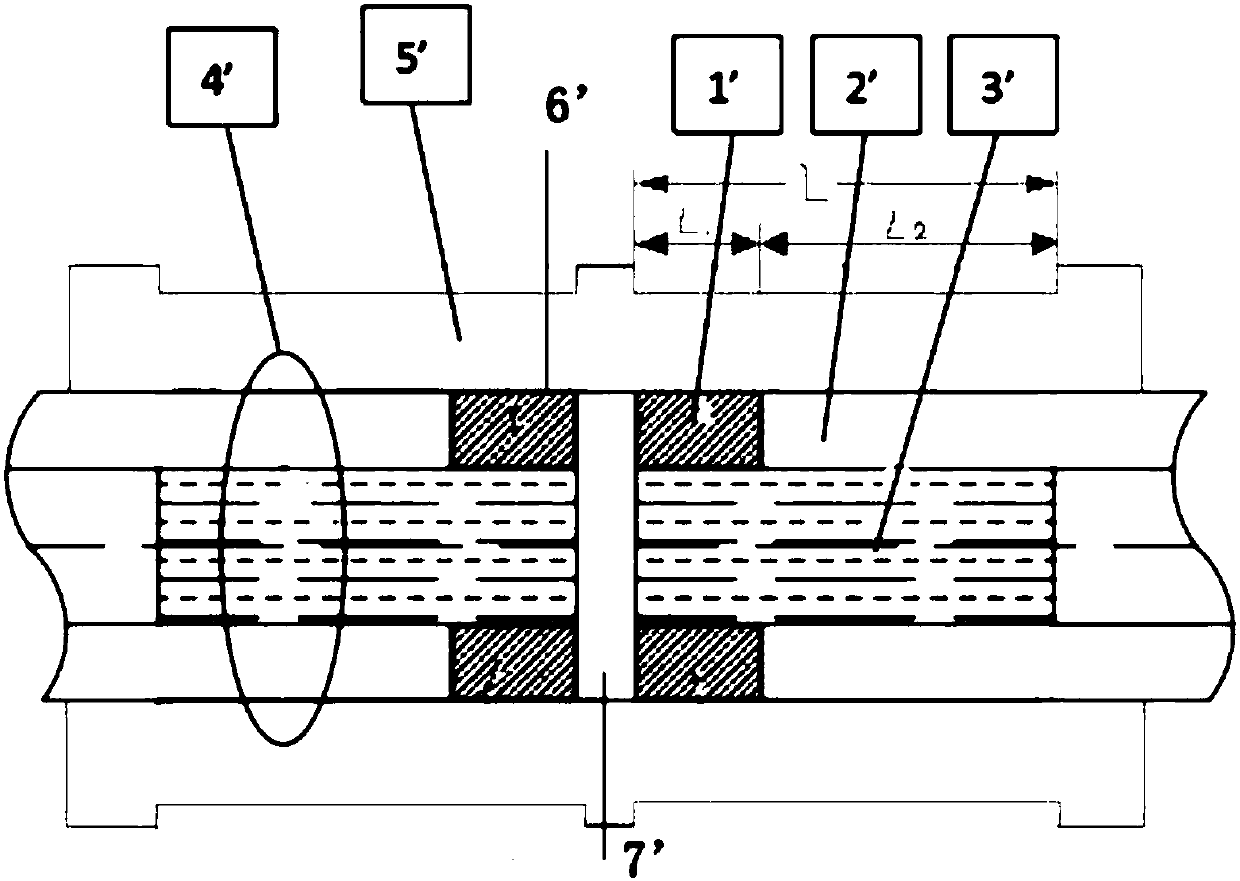
[0058] 1 Assume that the total number of conductor layers is N layers, and the internal welding layer is M layers, where M needs to be an integer. Before welding starts, it is necessary to ensure that the paint film of the crimped section has been removed and each layer has been fastened and fixed. Within the effective distance of crimping, counting from the center conductor to the M layer is defined as the area 3', such as figure 1 As shown in , layers M to N are defined as area 2'. Each layer of conductors in area 3' is brazed with gas flame of length L with welding rod A. After welding, it is ground into a uniform cylinder with a file and an electric sander, and the outer diameter is controlled to be consistent with the outer diameter of the M conductor. The conductors of each layer in the area 1' are carried out with the welding rod B to a length L 1 gas flame brazing.

[0059] according to Figure 4 and Figure 5 , R 1j It is the radial resistance of area 1', which...

Embodiment 2

[0074] 1 Assume that the total number of conductor layers is N layers, and the internal welding layer is M layers, where M needs to be an integer. Before welding starts, it is necessary to ensure that the paint film of the crimping section L has been removed and each layer has been fastened and fixed. Within the effective distance of crimping, counting from the center conductor to the M layer is defined as the area 3', such as figure 1 As shown in , layers M to N are defined as area 2'. Each layer of conductors in area 3' is gas flame brazed with electrode A to length L to fill the gaps and surfaces between the conductors of each layer with electrodes, and after welding, use a file and an electric sander to grind it into a uniform cylinder. The outer diameter of the control is consistent with the outer diameter of the M-layer conductor. The conductors of each layer in the area 1' are carried out with the welding rod B to a length L 1 gas flame brazing. The layers of condu...


PUM


Abstract

The invention belongs to the fields of a power transmission line and a power cable, and particularly relates to a crimping type cable conductor connector with a current sharing effect and a preparation method. Each layered insulating conductor consists of a first cylinder positioned in the centre of the conductor, and a second cylinder and a third cylinder with hollow-out central parts and arranged outside the first cylinder in a sleeving manner; the layered insulating conductor is inserted into a hollow conductor connecting pipe from the two ends of the conductor connecting pipe; in a crimping process, a crimping die surrounds the upper and lower sides of a crimping section of the conductor connecting pipe; and the cable conductor connector is extruded by die closing of the crimping die,and the conductor connecting pipe and the layered insulating conductor are subjected to micro deformation. By virtue of the crimping type cable conductor connector, the alternating current resistanceof the large-section cable conductor with the layered insulating structure in the conductor connector position can be lowered, so that the problem of temperature rise in the conductor and the connector positions when the large-section layered insulating conductor is applied can be overcome.

Description

technical field [0001] The invention belongs to the field of power transmission lines and power cables, and in particular relates to a crimping type cable conductor joint with a current equalizing function and a preparation method thereof. Background technique [0002] The skin effect, also known as the skin effect, refers to a phenomenon that when an alternating current passes through a conductor, the current distribution on the cross-section of the conductor is uneven due to induction, and the closer to the surface of the conductor, the greater the current density. This phenomenon is called "skin effect". The skin effect increases the effective resistance of the conductor. When the low-frequency current flows through a thin wire, the skin effect can be ignored, but the higher the frequency and the larger the conductor cross-section, the skin effect cannot be ignored. Especially at 800mm 2 The skin effect in the above-mentioned large cross-section cable conductor is the m...

Claims


Application Information

Patent Timeline
Patent Type & Authority Applications(China)
IPC IPC(8): H01R4/20H01R43/048
Inventor 杨黎明江贞星朱智恩马一力胡列翔郑海王少华
Owner STATE GRID CORP OF CHINA
Why Eureka
Try Eureka