Permanent magnet synchronous machine with flat-wire windings

a permanent magnet synchronous machine and stator technology, applied in the direction of windings, magnetic circuit rotating parts, magnetic circuit shapes/forms/construction, etc., can solve the problems of reduced copper filling factor in the slot of the electrical machine, increased coil cost, increased manufacturing complexity, etc., to reduce production complexity, increase copper filling factor, low additional loss factor

Inactive Publication Date: 2010-01-12
SIEMENS AG
View PDF21 Cites 11 Cited by
  • Summary
  • Abstract
  • Description
  • Claims
  • Application Information

AI Technical Summary

Benefits of technology

[0005]Against this background, the invention is based on the object of providing a permanent magnet synchronous machine which, with re

Problems solved by technology

Disadvantages here are the increased manufacturing complexity and the reduction in the copper filling factor in the slot of the electrical machine.
In or

Method used


Image

  • Permanent magnet synchronous machine with flat-wire windings
  • Permanent magnet synchronous machine with flat-wire windings
  • Permanent magnet synchronous machine with flat-wire windings

Examples


Embodiment Construction

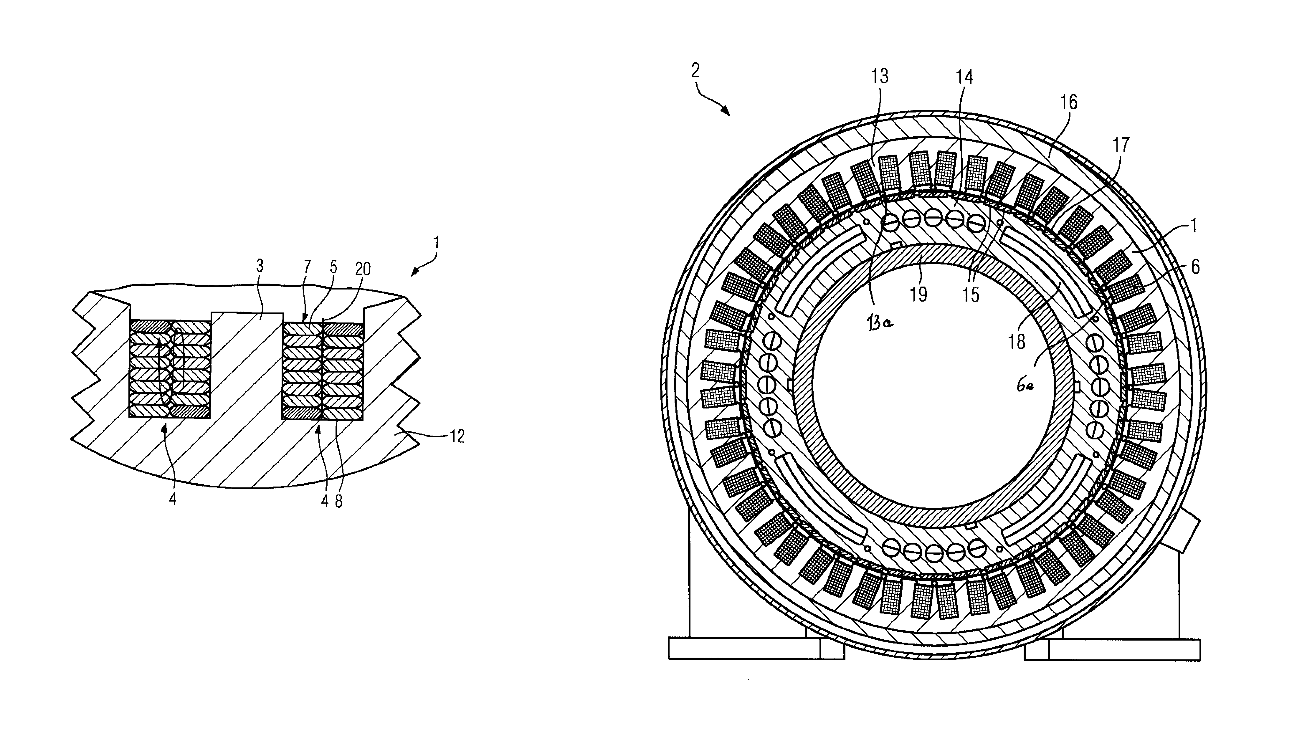
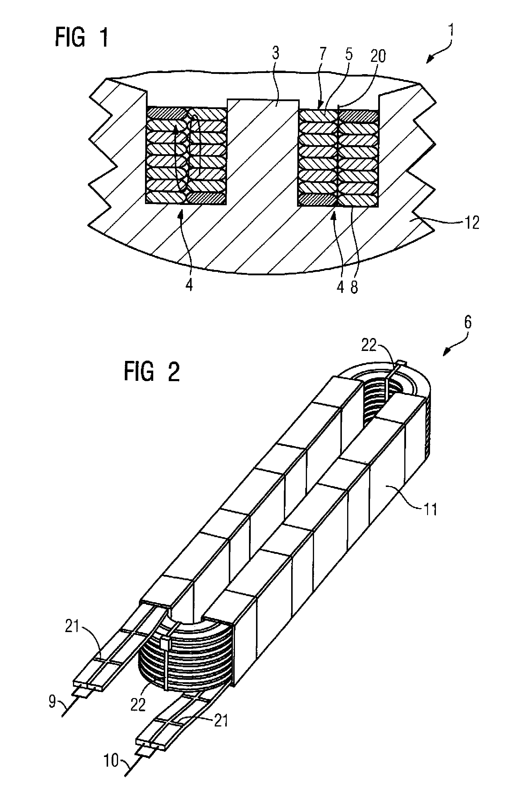
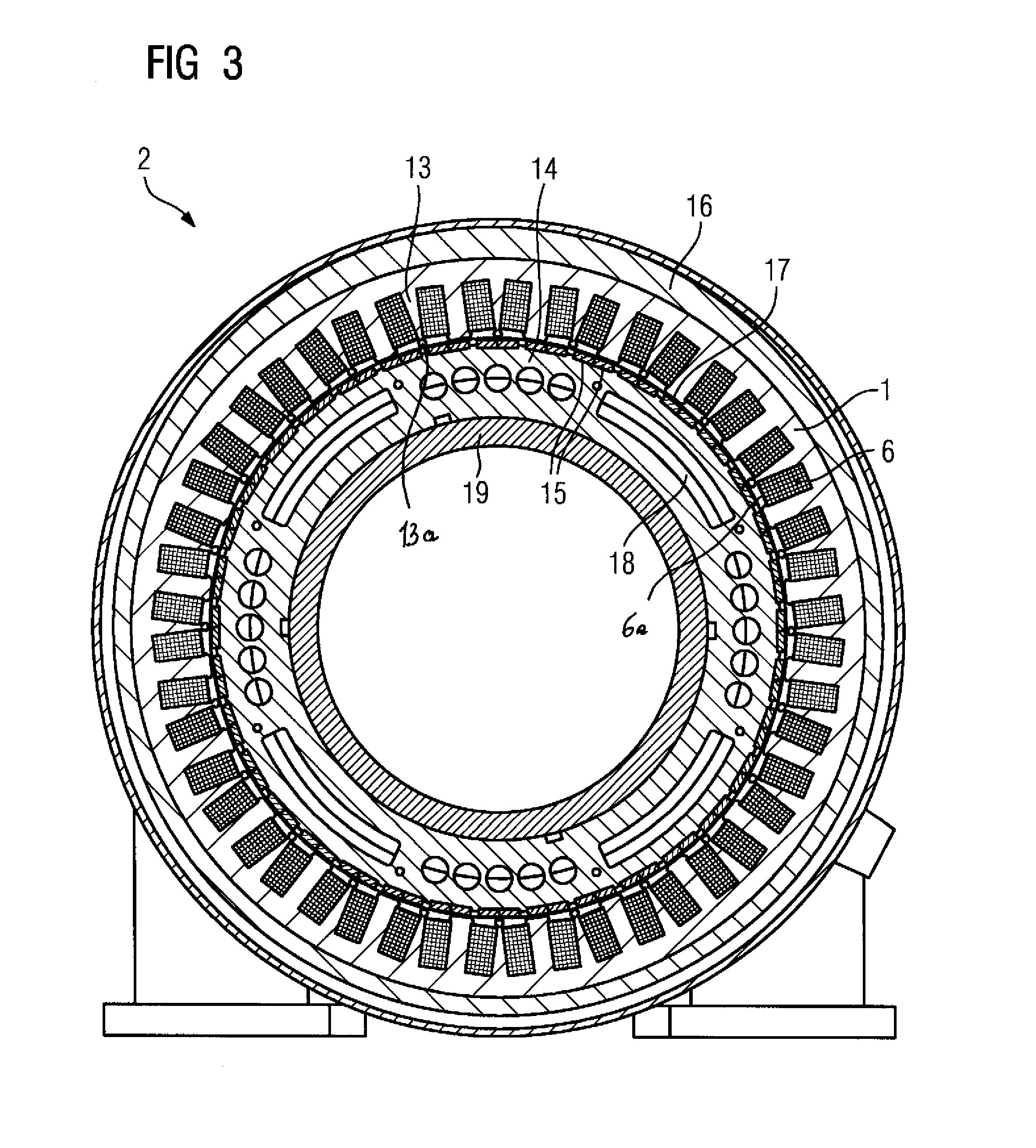
[0019]FIG. 1 shows a detailed view of a stator 1 of an electrical machine. This detailed view shows a tooth 3 with adjacent slots 4, which are designed to be parallel-flanked. The flat wires 5, which are arranged one above the other and adjacent to one another, are illustrated in the slots 4. A tooth-wound coil 6 having such a design is wound such that the winding layer 7 located directly on the tooth 3 extends from the slot base 8 radially toward the drilled stator hole, and the second layer also extends from the slot base 8 to the drilled stator hole. The adjacent winding layers 7 of the flat wires 5 in one slot can be connected electrically either in series or in parallel. As a result, two different turns numbers can be realized with a flat-wire dimension. In a parallel circuit, as is illustrated in principle in FIG. 2, for example, partial conductor insulation 20 is not absolutely necessary, since the flat wires 5 are designed to have an enamel insulation.

[0020]Such a tooth-woun...


PUM


Abstract

According to the invention, an improved copper filling in the slots (4) of a permanently-stimulated synchronous motor (2) may be achieved, whereby such a motor is disclosed, comprising a stator (1), with parallel-edged slots (4), provided with a winding system of flat wires (5), whereby the flat wires (5) each enclose a tooth (3) and are embodied as a tooth coil (6). The flat wires (5) are wound edgewise such that the narrower side of the flat wire (5) faces the tooth (3) and each tooth coil (6) comprises at least two layers of flat wires (5).

Description

BACKGROUND OF THE INVENTION[0001]The invention relates to a permanent magnet synchronous machine with a stator, which has parallel-flanked slots, which are provided with flat-wire windings, the flat-wire winding in each case surrounding a tooth and being in the form of a tooth-wound coil.[0002]In order to reduce skin effects and therefore the amount of heat entering the electrical machine, it is known to wind coils comprising a twisted or stranded conductor bundle comprising individual round wires. Disadvantages here are the increased manufacturing complexity and the reduction in the copper filling factor in the slot of the electrical machine.[0003]In order to avoid the abovementioned disadvantages, the coil can also be produced from copper pressed cable, but this results in increased costs for the coil.[0004]EP 1 255 344 A1 has disclosed a coil arrangement which is constructed from flat wire.SUMMARY OF THE INVENTION[0005]Against this background, the invention is based on the object...

Claims


Application Information

Patent Timeline
IPC IPC(8): H02K3/18
CPCH02K3/18H02K3/522H02K21/16H02K29/03
Inventor GEORG, KLAUSSCHUNK, HOLGERSTORATH, ALBRECHT
Owner SIEMENS AG
Why Eureka
Try Eureka