
Asymmetric dipole antenna

A dipole antenna and asymmetric technology, applied in the field of asymmetric dipole antennas, can solve the problems of poor communication quality, coupling effect of feed wiring and radiation part, insufficient gain value, etc., to meet the multi-frequency transmission capability, reduce production Complexity, the effect of improving applicability

Inactive Publication Date: 2013-04-10
ACCTON TECHNOLOGY CORPORATION
View PDF7 Cites 5 Cited by
  • Summary
  • Abstract
  • Description
  • Claims
  • Application Information

AI Technical Summary

Problems solved by technology

[0003] However, an overly wide feed-in wire will cause the signal it transmits to affect the signal of the radiation part, resulting in a coupling effect between the feed-in wire and the radiation part
Affects the impedance matching of the antenna elements, and the width of the frequency band is limited
If the distance between the feed wire and the radiation part is increased, the directivity of the omnidirectional antenna will be too high
On the other hand, although the loop circuit can obtain high impedance characteristics, the difficulty of the process will be relatively increased, which will reduce the yield of the antenna.
[0004] But in fact, no matter what kind of antenna, as long as it is installed in a terrain obstacle area (for example, a wall corner, ceiling, etc.), the gain value in a specific direction must be obviously insufficient, so that the communication quality is poor in signal transmission and reception.

Method used


Image

  • Asymmetric dipole antenna
  • Asymmetric dipole antenna
  • Asymmetric dipole antenna

Examples


Embodiment Construction

[0032] The preferred embodiments of the present invention are described in detail below with reference to the drawings.

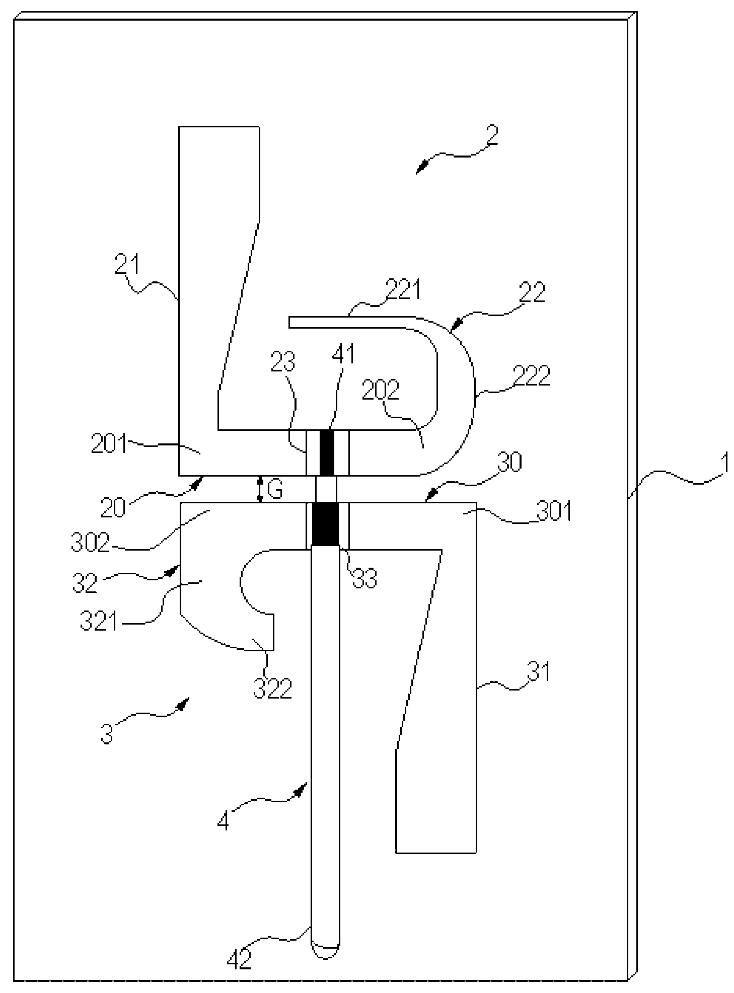
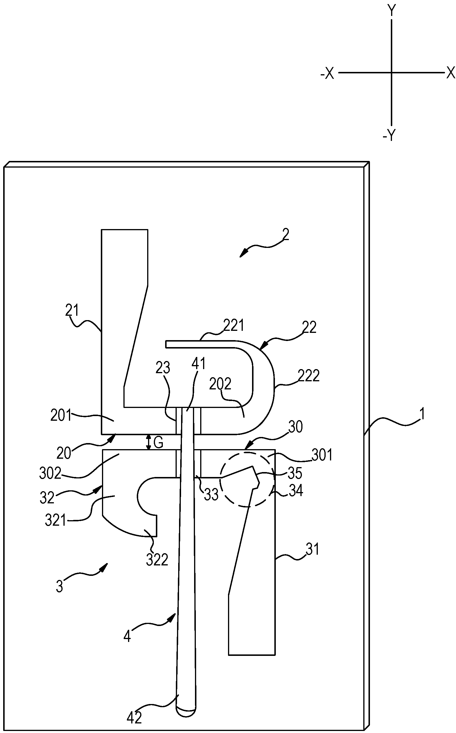
[0033] Firstly, please refer to FIG. 1 , which is a schematic diagram of the first structure of the embodiment of the asymmetric dipole antenna of the present invention. The asymmetric dipole antenna includes a substrate 1 , a radiation module 2 , a ground module 3 and a feeder unit 4 . Hereinafter, description will be made in conjunction with the reference direction shown in FIG. 1 .

[0034] The radiation module 2 is formed by disposing a first metal conductor on the substrate 1, and the grounding module 3 is formed by disposing a second metal conductor on the substrate 1. The formation methods are such as circuit board etching, metal liquid vapor deposition, and metal sputtering. , metal coating and other related methods are applicable without limitation.

[0035] The radiating module 2 has a radiating base 20 , which is elongated as an example, and a ...


PUM


Abstract

The invention discloses an asymmetric dipole antenna. A radiation module and a grounding module which are formed by metal conductors and distributed at intervals are arranged on a substrate of the antenna. The radiation module and the grounding module are respectively provided with a radiation base part and a grounding base part, and two ends of the two base parts respectively extend in reversed mode to form two radiation support arms and two grounding support arms. The first radiation support arm and the second radiation support arm are orthogonal on the radiation base part, and the second radiation support arm extends toward the first radiation support arm in bending mode to form an arc shape body with an opening facing to the first radiation support arm. The first grounding support arm and the second grounding support arm are orthogonal on the grounding base part, the second grounding support arm forms a hook-shaped body extending and bending toward the first grounding support arm, and a feeder unit is used for connecting the feed point and the grounding point of the two base parts in feeding mode. The asymmetric dipole antenna can generate enough gaining effect. The field shape is not apt to be influenced according to test, blind points are shallow, and a radiation field is round, so that the condition of bad communication quality cannot occur easily on signal transceiving. The asymmetric dipole antenna is simple in structure, low in manufacture complexity and the like.

Description

technical field [0001] The present invention relates to an antenna structure, in particular to an asymmetrical dipole antenna applicable to different types of wireless signal transmission. Background technique [0002] With today's antenna structure, the omnidirectional antenna is very useful for various wireless communication devices. This is because its radiation pattern allows good transmission and reception in a mobile unit. In order to increase the gain of the omnidirectional antenna and to improve the impedance matching of the antenna, the configuration usually uses a wider feed line or uses a loop loop to design the radiation part and the ground part. [0003] However, an overly wide feed-in wire will cause the transmitted signal to affect the signal of the radiation part, resulting in a coupling effect between the feed-in wire and the radiation part. The impedance matching of the antenna element is affected, and the width of the frequency band is limited. If the d...

Claims


Application Information

Patent Timeline
IPC IPC(8): H01Q1/36H01Q1/38H01Q1/48H01Q19/10
Inventor 李长荣
Owner ACCTON TECHNOLOGY CORPORATION
Learn More