Dust collector equipment

A dust collector and equipment technology, applied in the direction of preventing contact with live contacts, electrical components, coupling devices, etc., can solve the problems of unstable power supply connection, damage to the dust collector, power failure of the dust collector, etc., to achieve stable operation, reduce The effect of hidden safety hazards and high electrical safety

Inactive Publication Date: 2018-01-12
陈志桂
View PDF5 Cites 4 Cited by
  • Summary
  • Abstract
  • Description
  • Claims
  • Application Information

AI Technical Summary

Problems solved by technology

[0002] At present, the power of the dust collector is mainly to insert the plug connected with the dust collector directly into the jack of the socket. Although this matching method is simple to operate, the plug can still be pulled out directly after the plug is inserted into the jack. When the kick hits the cable connected between the plug and the dust collector by mistake, the plug will be separated from the socket, resulting in a sudden power failure of the dust collector. Therefore, the existing cooperation method has the risk of unstable power supply connection , easy to cause sudden power failure of the dust collector and damage

Method used


Image

  • Dust collector equipment
  • Dust collector equipment
  • Dust collector equipment

Examples


Embodiment Construction

[0021] All features disclosed in this specification, or steps in all methods or processes disclosed, may be combined in any manner, except for mutually exclusive features and / or steps.

[0022] Any feature disclosed in this specification (including any appended claims, abstract and drawings), unless expressly stated otherwise, may be replaced by alternative features which are equivalent or serve a similar purpose. That is, unless expressly stated otherwise, each feature is one example only of a series of equivalent or similar features.

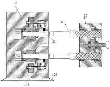
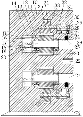
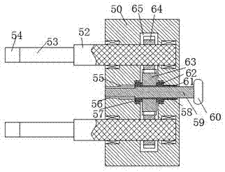
[0023] Such as Figure 1 to Figure 6 As shown, a dust collector device of the device of the present invention includes a power transmission seat 10 and a power transmission head 50 connected to the dust collector. In the power transmission head 50, inserting rods 51 are arranged oppositely up and down, and the inserting rods 51 includes a connecting rod 52 connected from right to left, a clamping rod 53 and a pushing rod 54, and the head 50 f...


PUM


Abstract

The invention discloses dust collector equipment. The dust collector equipment comprises a power transmission base and a power transmission head connected with a dust collector. Inserting bars are vertically and oppositely arranged in the power transmission head, and comprise powering-on bars, clamping bars and pushing bars, wherein the powering-on bars, the clamping bars and the pushing bars areconnected from right to left; first rotatable holes with leftward hole openings are vertically and oppositely formed in the power transmission head, first installing holes which vertically extend andare connected with the first rotatable holes in series are also formed in the power transmission head, the right ends of the powering-on bars are rotatably installed in the first rotatable holes, first secondary tooth gears fixedly connected with the powering-on bars are installed in the first installing holes, a first rotatable cylinder and a second rotatable cylinder are rotatably installed in the left end wall and the right end wall in the centers of the installing holes respectively, a first primary tooth gear matched with the first secondary tooth gears is fixedly connected between the first rotatable cylinder and the second rotatable cylinder, a center groove connected left and right is formed in the center of the power transmission head, and a spline hole extending left and right isformed in the center of the first primary tooth gear, the first rotatable cylinder and the second rotatable cylinder.

Description

technical field [0001] The invention relates to the field of dust collectors, in particular to dust collector equipment. Background technique [0002] At present, the power of the dust collector is mainly to insert the plug connected with the dust collector directly into the jack of the socket. Although this matching method is simple to operate, the plug can still be pulled out directly after the plug is inserted into the jack. When the kick hits the cable connected between the plug and the dust collector by mistake, the plug will be separated from the socket, resulting in a sudden power failure of the dust collector. Therefore, the existing cooperation method has the risk of unstable power supply connection , It is easy to cause damage to the dust collector due to sudden power failure. Contents of the invention [0003] Aiming at the deficiencies of the above technologies, the present invention proposes a dust collector device. [0004] A dust collector device of the pr...

Claims


Application Information

Patent Timeline
Patent Type & Authority Applications(China)
IPC IPC(8): H01R13/44H01R13/627H01R13/629H01R13/703
Inventor 陈志桂
Owner 陈志桂
Why Eureka
Try Eureka