
Relay base

A relay and base technology, applied in the field of relay bases, can solve the problems of waste control cabinet appearance, maintenance work interference, waste of artificial wires, etc., and achieve the effect of reducing repeated wiring, reducing waste, and saving labor.

Inactive Publication Date: 2018-01-16
WEIHAI FENGTAI NEW MATERIAL SCI & TECH
View PDF0 Cites 0 Cited by
  • Summary
  • Abstract
  • Description
  • Claims
  • Application Information

AI Technical Summary

Problems solved by technology

According to the current structure of the relay base, in the process of connecting multiple relays, the common points of each relay, such as the grounding point and power supply point, need to be connected in series with multiple wires, which wastes manpower, wires, labor, waste and causes control cabinets The overall appearance of the interior is messy and untidy, which brings great interference to the maintenance work

Method used


Image

  • Relay base
  • Relay base
  • Relay base

Examples


Embodiment Construction

[0009] The present invention will be described in detail below in conjunction with the accompanying drawings and embodiments.

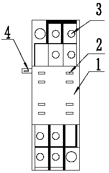
[0010] as attached figure 1 As shown, a relay base includes a base body 1 on which pin holes 2 and wire pressing holes 3 are provided.

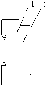
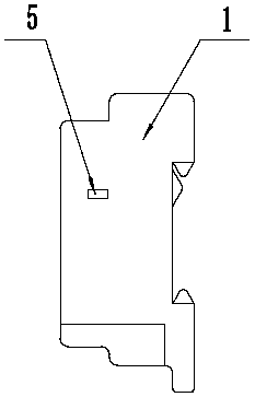
[0011] as attached figure 1 and attached figure 2 As shown, a common point plug 4 is provided on the left side of the seat body 1, as attached image 3 As shown, a common point jack 5 is provided on the right side of the seat body 1, and the common point plug 4 and the common point jack 5 are used as a group of common point connecting devices and one of the common point wires on the seat body 1 The pressure hole 3 is electrically connected.

[0012] When multiple relays are installed side by side, install the rightmost relay base first, and then install from the right to the left. The common point plug on each relay base is inserted into the common point jack of the adjacent relay base on its left in turn. Ther...


PUM


Abstract

The invention belongs to the technical fields of electric components and parts, and aims to solve the technical problem that each relay in a control cabinet is disordered in wire connection, labor-consuming and material-consuming at present. The invention provides a relay base; the relay base comprises a base; pin holes and wire pressing holes are formed in the base; the relay base is characterized in that at least one common point jack is formed in the side surface on one side of the base while a common point plug corresponding to the common point jack is arranged on the side surface on the other side of the base; and each common point jack and the corresponding common point plug are electrically connected with one corresponding common point wire pressing hole. The relay base has the beneficial effects of reducing repeated wire connection of a common line in wire connection, saving labor force, lowering wrong connection rate, reducing material of common wire connection and lowering waste; and meanwhile, by virtue of tight relay combination, relatively less wiring, attractive overall structure and convenience in overhaul can be realized.

Description

technical field [0001] The invention belongs to the technical field of electrical components, and in particular relates to a relay base. Background technique [0002] At present, in the design and production of the control cabinet, a large number of relays are needed. In order to facilitate the replacement of the relays, there are multiple rows of relay bases on the internal crosspiece of the control cabinet. figure 1 As shown, the relay base includes a base body 1 on which pin holes 2 are provided, and wire pressing holes 3 are provided on the relay base body at both ends of the pin hole 2 . During use, the pin of the relay is inserted on the pin hole 2, and the control wire and the power supply wire are connected inside the wire pressing hole 3. According to the current structure of the relay base, in the process of connecting multiple relays, the common points of each relay, such as the grounding point and power supply point, need to be connected in series with multiple ...

Claims


Application Information

Patent Timeline
Patent Type & Authority Applications(China)
IPC IPC(8): H01H50/14H01H50/02
Inventor 钱国峰刘海庆宋文进
Owner WEIHAI FENGTAI NEW MATERIAL SCI & TECH
Learn More