Anti-blocking feeding device for pig raising

An anti-clogging and movable installation technology, applied in the field of pig raising, can solve the problems of clogging of the discharge pipe, blockage of the discharge pipe, inconvenience in use, etc., and achieve the effects of improving speed, improving stability and being convenient to use.

Inactive Publication Date: 2018-01-19
耒阳市晓田牧业有限责任公司
0 Cites 1 Cited by

AI-Extracted Technical Summary

Problems solved by technology

[0003] The purpose of the present invention is to provide an anti-clogging pig feeding device, which has the advantages of avoiding the blockage of the disch...

Method used

Please refer to Fig. 1-2, a kind of anti-clogging feeding device for raising pigs, comprising casing 1, both sides of casing 1 bottom are all fixedly connected with supporting leg 21, and the bottom of supporting leg 21 is fixedly connected with antiskid Pad 22, by arranging support leg 21 and anti-slip pad 22, can improve the stability of this device, the top of box body 1 front surface is provided with placement opening 2, and the front surface of box body 1 and the position of corresponding placement opening 2 pass through Dodge door 3 is installed movablely, and the right side of dodge door 3 positive surface is fixedly connected with handle 24, and the surface of handle 24 is socketed with anti-slip cover 25, by setting handle 24 and anti-slip cover 25, can facilitate people to open dodge door 3, The bottom of the right side of the box body 1 is connected with a discharge pipe 4, and a discharge valve 5 is arranged on the discharge pipe 4;
The top of casing 1 offers through hole 6, and the inside of through hole 6 is provided with elevating rod 7, and the top of elevating rod 7 passes through hole 6 and extends to the inside of casing 1 and is fixedly installed with motor 8, The output end of motor 8 is fixedly connected with rotating rod 9, and the top and the bottom of rotating rod 9 both sides are all fixedly connected with dispersing rod 10, and dispersing rod 10 is provided with acceleration hole 23, and each dispersing rod 10 surface acceleration holes 23 The number is three, and the speed of dispersing the feed can be improved by setting the accelerating hole 23. The inside of the box 1 and the bottom of the dispersing rod 10 are fixe...

Abstract

The invention discloses an anti-blocking feeding device for pig raising. The anti-blocking feeding device comprises a box body, wherein the top of the front surface of the box body is provided with aplacing opening; a movable door is movably arranged in a position, corresponding the placing opening, of the front surface of the box body through a hinge; the bottom of the right side of the box bodyis communicated with a discharging pipe; a discharging valve is arranged on the discharging pipe; the top of the box body is provided with a through hole; an ascending and descending rod is arrangedinside the through hole in a penetrating way; the top of the ascending and descending rod passes through the through hole, extends into the inside of the box body and is fixedly provided with a motor;the output end of the motor is fixedly connected with a rotating rod. The anti-blocking feeding device has the advantages that through the matching of the ascending and descending rod, the motor, therotating rod, a dispersion rod, a fixing rod, a straight gear plate, an electric telescopic rod, a movable rod, a support rod and a fan-shaped gear plate, the motor can vertically move, so that the motor can drive the rotating rod and the dispersion rod for dispersing agglomerated feed; the discharging pipe blockage by the agglomerated feed is avoided; the use is convenient.

Application Domain

Animal feeding devices

Technology Topic

EngineeringVALVE PORT

Image

  • Anti-blocking feeding device for pig raising
  • Anti-blocking feeding device for pig raising

Examples

  • Experimental program(1)

Example Embodiment

[0016] The technical solutions in the embodiments of the present invention will be clearly and completely described below in conjunction with the accompanying drawings in the embodiments of the present invention. Obviously, the described embodiments are only a part of the embodiments of the present invention, rather than all the embodiments. Based on the embodiments of the present invention, all other embodiments obtained by those of ordinary skill in the art without creative work shall fall within the protection scope of the present invention.
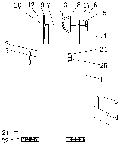
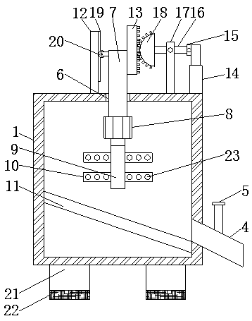
[0017] See Figure 1-2 , An anti-clogging feeding device for pigs, comprising a box body 1, both sides of the bottom of the box body 1 are fixedly connected with support legs 21, the bottom of the support legs 21 are fixedly connected with a non-slip pad 22, by setting the support legs 21 and The anti-skid pad 22 can improve the stability of the device. The top of the front surface of the box 1 is provided with a placement opening 2, and the front surface of the box 1 is movably installed with a movable door 3 through a hinge to the position corresponding to the placement opening 2. A handle 24 is fixedly connected to the right side of the front surface of the door 3, and a non-slip sleeve 25 is sleeved on the surface of the handle 24. By providing the handle 24 and the non-slip sleeve 25, people can easily open the movable door 3, and the bottom of the right side of the box 1 is connected with Discharge pipe 4, which is provided with a discharge valve 5;
[0018] The top of the box 1 is provided with a through hole 6, the inside of the through hole 6 is provided with a lifting rod 7, and the top of the lifting rod 7 passes through the through hole 6 and extends to the inside of the box 1 is fixedly installed with a motor 8. The output end is fixedly connected with a rotating rod 9. The top and bottom of both sides of the rotating rod 9 are fixedly connected with a dispersing rod 10. The dispersing rod 10 is provided with acceleration holes 23, and the number of acceleration holes 23 on the surface of each dispersing rod 10 is three. One, by providing the accelerating hole 23, the speed of dispersing the feed can be increased. The inside of the box 1 and located at the bottom of the dispersing rod 10 is fixedly connected with a guide plate 11, and the top of the lifting rod 7 passes through the through hole 6 and extends to the through hole 6. Outside, the top of the box 1 and the left side of the through hole 6 is fixedly connected with a fixed rod 12, the top of the left side of the lifting rod 7 is slidingly connected with the right side of the fixed rod 12, and the right side of the fixed rod 12 is fixedly connected with a sliding Rail 19, the top of the left side of the lifting rod 7 is movably installed with a roller 20 through a bracket, the roller 20 is slidably connected to the slide rail 19, the top of the right side of the lifting rod 7 is fixedly connected with a straight tooth plate 13, and the right side of the top of the box 1 is fixed An electric telescopic rod 14 is installed. The top of the left side of the electric telescopic rod 14 is fixedly connected with a connecting seat 15, and the left side of the connecting seat 15 is movably connected with a movable rod 16 through a rotating shaft. The top of the box 1 is located on the left side of the electric telescopic rod 14. A support rod 17 is fixedly connected to the side. The top of the front surface of the support rod 17 is movably connected to the movable rod 16 through a pin. The left end of the movable rod 16 is fixedly connected with a sector-shaped tooth plate 18 that is used in conjunction with the straight tooth plate 13 through the lifting rod 7. , The motor 8, the rotating rod 9, the dispersing rod 10, the fixed rod 12, the straight tooth plate 13, the electric telescopic rod 14, the movable rod 16, the support rod 17 and the sector tooth plate 18 can make the motor 8 move up and down, thereby The motor 8 drives the rotating rod 9 and the dispersing rod 10 to disperse the agglomerated feed, which prevents the agglomerated feed from blocking the discharge pipe 4, which is convenient to use.
[0019] When in use, the user opens the movable door 3 and puts the feed into the box 1, the user then starts the motor 8 and the electric telescopic rod 14, the motor 8 drives the rotating rod 9 and the dispersion rod 10 to rotate, and the electric telescopic rod 14 is connected through The seat 15 drives the movable rod 16 to swing. When the movable rod 16 swings, the sector-shaped tooth plate 18 drives the straight tooth plate 13 to move up and down. When the straight tooth plate 13 moves up and down, the lifting rod 7 moves up and down. The up and down movement of the lifting rod 7 can increase the dispersion rod. 10 The efficiency of dispersing the feed, the user opens the discharge valve 5 again, and the feed can flow out through the discharge pipe 4.
[0020] To sum up: the anti-clogging feeding device for pig raising is through the lifting rod 7, the motor 8, the rotating rod 9, the dispersing rod 10, the fixed rod 12, the straight tooth plate 13, the electric telescopic rod 14, the movable rod 16, and the support The cooperation of the rod 17 and the fan-shaped toothed plate 18 solves the problem that the current feeding device often blocks the discharge pipe due to the agglomeration of feed and is inconvenient to use.
[0021] Although the embodiments of the present invention have been shown and described, those of ordinary skill in the art can understand that various changes, modifications, and substitutions can be made to these embodiments without departing from the principle and spirit of the present invention. And variations, the scope of the present invention is defined by the appended claims and their equivalents.

PUM

no PUM

Description & Claims & Application Information

We can also present the details of the Description, Claims and Application information to help users get a comprehensive understanding of the technical details of the patent, such as background art, summary of invention, brief description of drawings, description of embodiments, and other original content. On the other hand, users can also determine the specific scope of protection of the technology through the list of claims; as well as understand the changes in the life cycle of the technology with the presentation of the patent timeline. Login to view more.

Similar technology patents

Disposable medical-examination light

ActiveUS20090097236A1good visualizationeasy to use
Owner:UTAH MEDICAL PRODS

Patient positioning support structure

ActiveUS20120198625A1easy to useinexpensive to make
Owner:WARSAW ORTHOPEDIC INC

Classification and recommendation of technical efficacy words

  • Improve stability
  • easy to use

Laser assisted total joint arthroplasty

InactiveUS20090234360A1easy to use
Owner:ALEXANDER VLADIMIR

Enclosure for a portable hemodialysis system

ActiveUS20090114582A1easy to use
Owner:DEKA PROD LLP
Why Eureka
Try Eureka