
Eureka
For R&D, Eureka makes reading and utilizing patents & technical documents easy.
Eureka AIR
Designed for self-driven R&D workflows. Generate viable solutions, solve complex R&D challenges, empower your innovation with AI.

Eureka Materials
Designed for material experts only. Revolutionize your material R&D, from search, analyze, to developing new materials.

TechResearch
Generate reliable direction feasibility study reports for your R&D in just a few steps.

TechSeek
Discover and master advanced knowledge NOW. Basics, ideas, possibilities, all at once.

TechMind
As an expert in R&D Theories, TechMind can generates customized viable solutions instantly.

TechRisk
Analyze your overall solution with one click, know your potential R&D risks in advance.

TechMonitor
Get weekly tech updates, stay abreast of the latest tech innovations and key insights.
Standing device capable of changing directions at will
A standing surface, any angle technology, applied in the field of electricity, can solve the problems of easy damage, inconvenient use, poor flexibility, etc., to achieve the effect of increasing the safety factor, easy to adjust the angle, convenient and flexible operation
- Summary
- Abstract
- Description
- Claims
- Application Information
AI Technical Summary
Problems solved by technology
Method used
Image

Examples
Embodiment 1
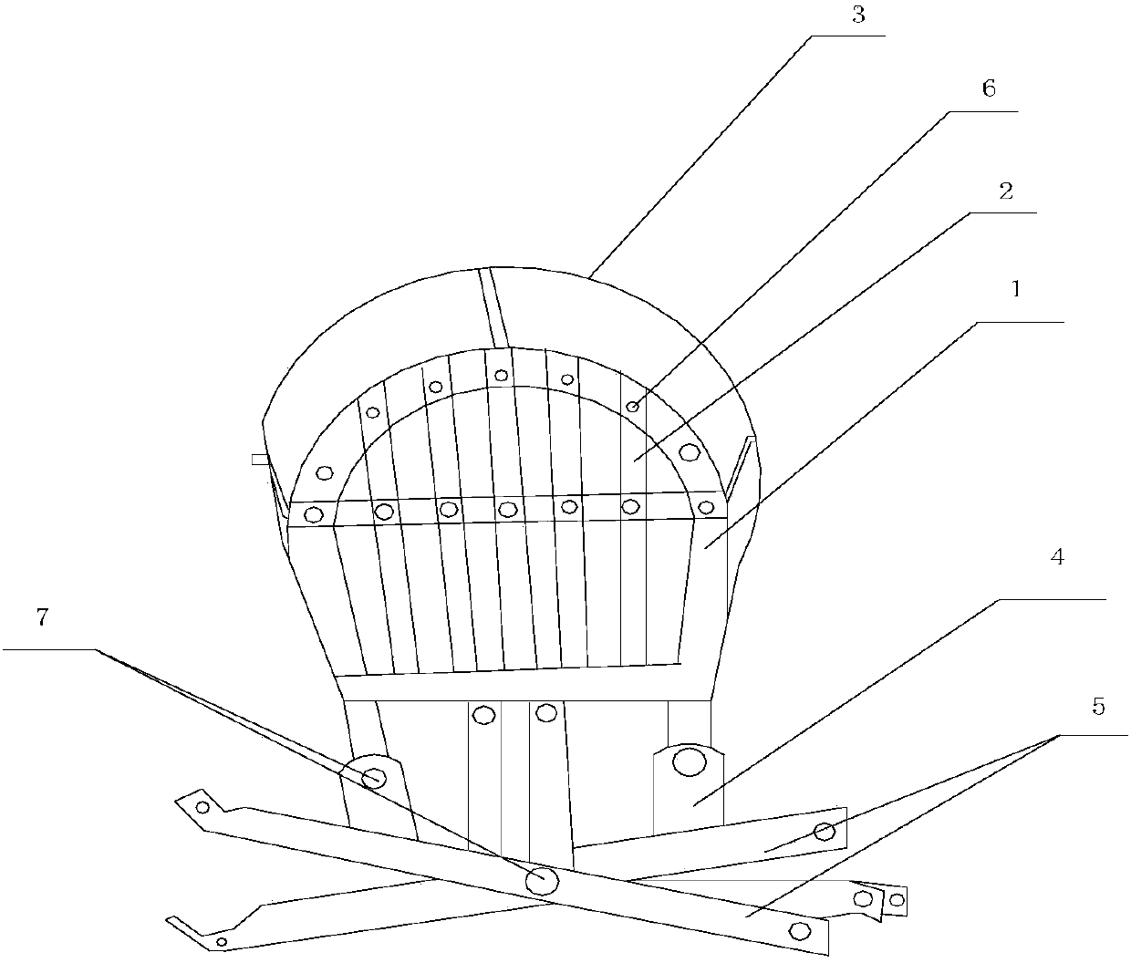
[0019] Such as figure 1 As shown, the present invention includes a standing device capable of swinging in any direction, including a standing surface 1, a connecting bracket 4, and a plurality of mounting plates 5. The rotating part 7, the standing surface 1 and a plurality of mounting plates 5 can rotate around the rotating part 7, and a fence 3 for protection is also set on the standing surface 1, and the standing surface 1 is crossed by a closed cavity and a plurality of bolts 6 It consists of steel bars 2 fixed on the closed cavity; the midpoints of the multiple mounting plates 5 are connected to the rotating parts 7, and each mounting plate 5 can rotate around the rotating parts 7 at any angle. Both ends of 5 are provided with mounting holes for mounting hoops.
[0020] When the power transmission equipment located outdoors needs to be maintained, first use the external crawling tool to reach the height that needs to be maintained, and then rotate the connecting bracket ...
Embodiment 2
[0022] This embodiment is preferably as follows on the basis of Embodiment 1: each mounting board works independently of each other. They do not affect each other. If one of the installation boards is abnormal, other installation boards can be used, which is economical and practical.
[0023] Anti-slip lines are also provided on the surfaces of the standing surface 1 and the fence 3 . The maintenance personnel stand on it, and the friction force is large and it is not easy to slip.
[0024] The fence 3 is an arc-shaped structure, and a hook is also provided on the end surface of the fence 3 . The setting of the hook can be additionally passed through the hook with a rope, and then put on the pole to further improve the safety of the platform.
PUM
 Abstract
Description
Claims
Application Information
 - R&D Engineer
- R&D Manager
- IP Professional
- Industry Leading Data Capabilities
- Powerful AI technology
- Patent DNA Extraction
Browse by: Latest US Patents, China's latest patents, Technical Efficacy Thesaurus, Application Domain, Technology Topic, Popular Technical Reports.
© 2024 PatSnap. All rights reserved.Legal|Privacy policy|Modern Slavery Act Transparency Statement|Sitemap|About US| Contact US: help@patsnap.com