Conveying mechanism

A conveying mechanism and conveying roller technology, which is applied in the field of solar photovoltaic module frame profile detection equipment, can solve the problems of affecting conveying and the inability to adjust the distance between two roller shafts.

Inactive Publication Date: 2018-01-19
JIANGSU ZHONGQIRUICHI IND ROBOT AUTOMATION CO LTD
View PDF7 Cites 1 Cited by
  • Summary
  • Abstract
  • Description
  • Claims
  • Application Information

AI Technical Summary

Problems solved by technology

[0002] The conveyor mechanism of the existing solar photovoltaic frame cutting equipment includes several conveyors, each conveyor belt is connected by two r

Method used


Image

  • Conveying mechanism
  • Conveying mechanism

Examples


Embodiment Construction

[0013] The present invention is described in further detail now in conjunction with accompanying drawing. These drawings are all simplified schematic diagrams, which only illustrate the basic structure of the present invention in a schematic manner, so they only show the configurations related to the present invention.

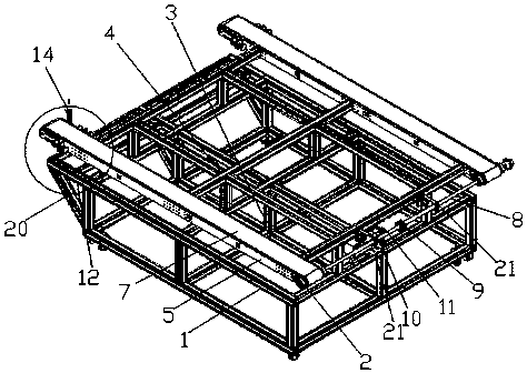
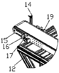
[0014] Such as figure 1 with figure 2 As shown, a conveying mechanism includes a frame base 1 and several conveying rollers 2. A mounting frame 4 is connected to the top of the frame base 1 through several support rods 3. Several groups of conveying roller mounting plates 5 are horizontally arranged on the mounting frame 4. Several groups Conveying roller mounting plates 5 are arranged in parallel, and conveying rollers 2 are installed at both ends of each conveying roller mounting plate 5, and a conveyor belt 7 is connected between the two conveying rollers 2 on each conveying roller mounting plate 5;

[0015] One end of two adjacent groups of conveying ro...


PUM


Abstract

The invention discloses a conveying mechanism. The conveying mechanism comprises a frame base and multiple conveying rollers; a mounting frame is connected above the frame base through multiple support rods; multiple sets of conveying roller mounting plates are transversely arranged on the mounting frame, and are arranged in parallel; conveying rollers are mounted at two ends of each conveying roller mounting plate; and a conveying belt is connected between two conveying rollers on each conveying roller mounting plate. The conveying mechanism is reasonable in design and suitable for popularization and application.

Description

technical field [0001] The invention relates to a conveying mechanism, which is mainly used for detecting equipment for frame profiles of solar photovoltaic modules. Background technique [0002] The conveyor mechanism of the existing solar photovoltaic frame cutting equipment includes several conveyors, each conveyor belt is connected by two roller shafts, and the distance between the two roller shafts cannot be adjusted, but if the conveyor belt is too loose after long-term use , will affect the transmission. Contents of the invention [0003] In order to overcome the above-mentioned deficiencies, the present invention provides a conveying mechanism, which includes a frame base and several conveying rollers. A mounting frame is connected above the frame base through several support rods. Several groups of conveying roller mounting plates are horizontally arranged on the mounting frame. Several groups of conveying rollers The roller mounting plates are arranged in parall...

Claims


Application Information

Patent Timeline
IPC IPC(8): B65G23/44
Inventor 傅佳明王建丰
Owner JIANGSU ZHONGQIRUICHI IND ROBOT AUTOMATION CO LTD
Why Eureka
Try Eureka