Water energy turbine and pump integration machine

A technology of water energy pump and integrated machine, applied in the direction of machine/engine, pump, pump components, etc., can solve the problems of complex installation and large floor space, and achieve overall reduction in volume, simple structure, assembly and post-maintenance. convenient effects

Pending Publication Date: 2020-01-17
JIANGXI RONGHE SPECIAL FIRE EQUIP MFG
View PDF0 Cites 0 Cited by
  • Summary
  • Abstract
  • Description
  • Claims
  • Application Information

AI Technical Summary

Problems solved by technology

The mechanical pump-in proportional mixing device that appears on the market now uses a sliding vane or screw type water turbine and a foam liquid pump connected by a coupling. The pump unit of the mixing device is relatively complicated to install and occupies a large area.

Method used


Image

  • Water energy turbine and pump integration machine
  • Water energy turbine and pump integration machine

Examples


Embodiment 1

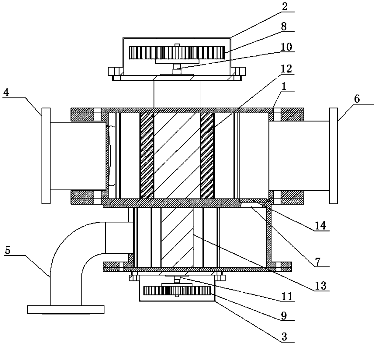
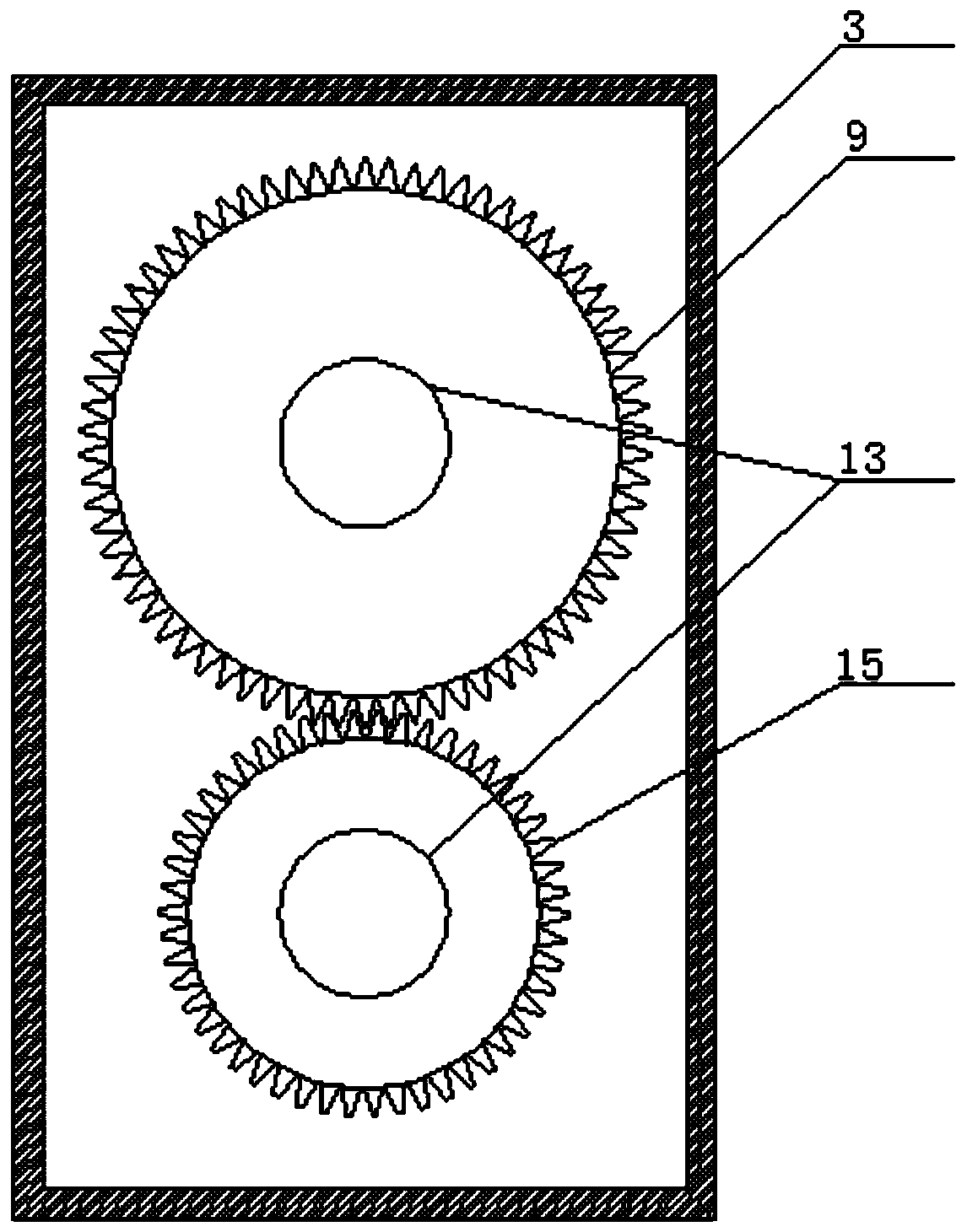
[0015] Embodiment 1, see figure 1 and figure 2 , a water energy machine pump integrated machine, including a housing 1, a water turbine gear box 2, a foam pump gear box 3, a fire water inlet 4, a foam liquid inlet 5, a mixed liquid outlet 6, a foam liquid outlet 7, and a water turbine transmission gear 8 , foam pump transmission gear 9, machine pump connecting shaft 10, foam pump connecting shaft 11, water turbine impeller 12, foam pump rotor 13, non-return device 14, foam pump driven pinion 15; The foam pump and the water turbine share a shell 1, and the drive shafts of the water turbine impeller 12 located on the top of the shell 2 and the foam pump rotor 13 are connected by the same machine-pump connecting shaft 10. As long as the water turbine impeller 12 rotates, it is the same The machine pump connecting shaft 10 can directly drive the foam pump rotor 13 to rotate, and driven by the foam pump gearbox 3, the upper and lower rotors of the foam pump rotate, and the foam l...

Embodiment 2

[0016] Example 2, see figure 1 A non-return device 14 is provided at the outlet 7 of the foam liquid to prevent the water on the turbine side from entering the foam pump side, so as to ensure that the foam liquid is mixed with water at the outlet of the water turbine to form a foam mixture.

Embodiment 3

[0017] Example 3, see figure 1 , figure 2 The water turbine impeller 12 and the foam pump rotor 13 are two groups, which are distributed symmetrically up and down. The two rotors of the foam pump rotate up and down, and the foam liquid is squeezed between the two rotors, so that the foam liquid generates a certain pressure and passes through figure 1 The outlet of the middle foam liquid is injected into the side outlet of the water turbine, which is convenient for adjusting the foam liquid.


PUM


Abstract

The invention relates to a water energy turbine and pump integration machine. An existing mechanical pumping proportional mixing device on the market adopts a mixed device pump set formed by connecting a slide piece type or screw rod type water turbine with a foam liquid pump through a coupling, so that the installation is more complex, and the floor area is large. In the water energy turbine andpump integration machine, a water turbine impeller positioned at the upper part of a shell is connected with a transmission shaft of a foam pump rotor by adopting the same turbine pump connecting shaft; a water turbine transmission gear and a foam pump transmission gear are respectively arranged in a water turbine gear box and a foam pump gear box; the water turbine transmission gear is fixedly connected with a turbine pump connecting shaft; and the foam pump transmission gear is fixedly connected with the turbine pump connecting shaft through a foam pump connecting shaft. The machine has thefollowing advantages: the water energy turbine and pump integration machine adopts an integral structure design of a water turbine and a foam pump, so that the total size is greatly reduced; and the water energy turbine and pump integration machine is simple in structure and more convenient for assembly and later maintenance.

Description

technical field [0001] The invention relates to the technical field of fire-fighting equipment, and is an important component of a mechanically pumped foam proportional mixing device, in particular to a water-energy-machine-pump integrated machine. Background technique [0002] The mechanically pumped foam proportional mixing device is a new type of foam mixing device that replaces the traditional balanced proportional mixing device in the field of fire protection. It has the characteristics of low energy consumption, low failure rate, simple operation, and convenient maintenance. In major new petrochemical projects. The closed water turbine driven pump unit is the core component of the mechanically pumped foam proportional mixing device. The hydraulically driven water turbine rotates to drive the foam liquid pump to rotate. The water in the water turbine is mixed in a certain proportion to form a foam mixture. The mechanical pump-in proportional mixing device that appears...

Claims


Application Information

Patent Timeline
Patent Type & Authority Applications(China)
IPC IPC(8): F04C13/00F04C2/14F04C15/00F03B13/00
CPCF03B13/00F04C2/14F04C13/001F04C15/008
Inventor 涂建新吴洋
Owner JIANGXI RONGHE SPECIAL FIRE EQUIP MFG
Why Eureka
Try Eureka