Double-split-flow turbine steam-inlet diversion structure

A split turbine and steam inlet technology, which is applied in the direction of blade support components, stators, engine components, etc., can solve the problems of poor stability and reliability of steam axial split flow, high loss, unstable aerodynamic boundary of steam vortex, etc.

Active Publication Date: 2018-01-19
DONGFANG TURBINE CO LTD
View PDF5 Cites 4 Cited by
  • Summary
  • Abstract
  • Description
  • Claims
  • Application Information

AI Technical Summary

Problems solved by technology

However, because the split cavity between the forward and reverse first-stage impellers (that is, the impellers on both sides) is very large, and the walls of the impellers on both sides of the split cavity are vertical, it cannot control the flow rate in the split cavity. The steam vortex is well controlled, so that the steam vortex in the split cavity is extremely unstable under the impact of the subsequent steam, that is, the steam vortex in the split cavity acts as an unstable aerodynamic boundary for the subsequent steam inflow, resulting in the steam axis The stability and reliability of the split flow are poor; at the same time, ...

Method used


Image

  • Double-split-flow turbine steam-inlet diversion structure
  • Double-split-flow turbine steam-inlet diversion structure
  • Double-split-flow turbine steam-inlet diversion structure

Examples


Embodiment Construction

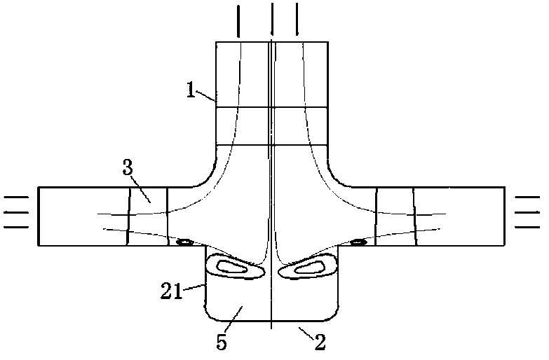
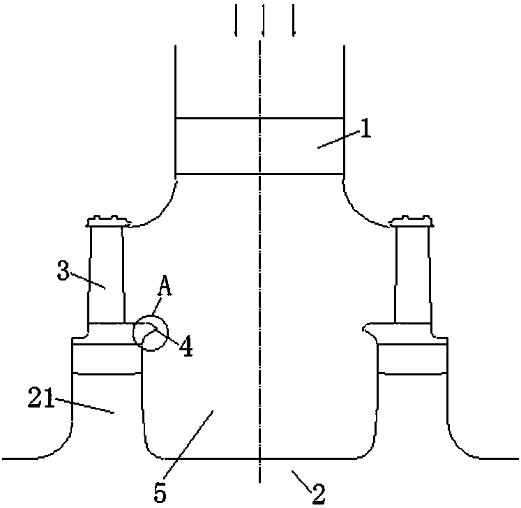
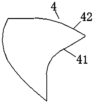
[0013] The invention relates to turbine technology, in particular to a steam inlet diversion structure of a double split flow turbine. Below in conjunction with the accompanying drawings of the description - that is figure 2 , image 3 and Figure 4 The technical content of the present invention is described in detail and specifically.

[0014] see figure 2 , image 3 and Figure 4 As shown, the present invention includes a first-stage vane 1 and a wheeled rotor 2 that are assembled together correspondingly.

[0015] Wherein, the first-stage stationary vane 1 is a radial-flow stationary vane.

[0016] The two sides of the part of the wheel rotor 2 corresponding to the first-stage stationary blade 1 have radially protruding impellers 21 for assembling the moving blades 3 , and the positive and negative first-stage moving blades 3 are correspondingly assembled on their corresponding on the rim of the impeller 21.

[0017] The split cavity 5 is enclosed between the firs...


PUM


Abstract

The invention discloses a double-split-flow turbine steam-inlet diversion structure. The double-split-flow turbine steam-inlet diversion structure comprises a runoff type first-level stator and a wheel type rotor which are correspondingly assembled together. The two sides of the portions, corresponding to the first-level stator, of the wheel type rotor are correspondingly provided with impellers protruding in the radial direction and being used for assembling movable blades. Diversion mold cavities are defined by the first-level static blade, the wheel type rotor and the corresponding movableblades. The movable blade root positions of the two sides of each diversion mold cavity are correspondingly provided with streamline sharply protruding steam inlet diversion portions extending to thediversion mold cavity. The steam inlet diversion portions of the two sides of each diversion mold cavity are oppositely formed. The steam inlet diversion portion on each side and the blade root steaminlet side face and the blade root plane of the corresponding movable blade are in smooth transition in the form of the streamline profile structure. By the adoption of the double-split-flow turbine steam-inlet diversion structure, the stability and reliability of bidirectional conversion from runoff steam to axial flow can be guaranteed effectively; and meanwhile flow separation generated beforethe diverted steam enters the movable blades can be effectively prevented, the uniformization of the steam flow entering the corresponding movable blades is guaranteed, and the acting loss of the movable blades is lowered.

Description

technical field [0001] The invention relates to turbine technology, in particular to a steam inlet diversion structure of a double split flow turbine. Background technique [0002] With the development and progress of turbine technology, radial flow vanes are gradually introduced into large steam turbines due to their specific technical advantages. In steam turbine technology, the radial flow vane is usually arranged as the first-stage vane, so that the steam is converted into axial flow through the radial inflow of the first-stage vane, and the axial double-split flow is realized. [0003] For the double-splitter turbine technology of the wheel rotor, the radial flow first-stage stationary blades assembled together, the wheel rotor and the moving blades enclose the split cavity. see figure 1 As shown, specifically, the two sides of the part of the wheeled rotor 2 corresponding to the first-stage vane 1 respectively have radially protruding impellers 21 for assembling the ...

Claims


Application Information

Patent Timeline
IPC IPC(8): F01D5/30F01D5/06F01D9/02
Inventor 张晓丹钟刚云邓国梁钟主海王姗王华强杨恒熠王娟丽
Owner DONGFANG TURBINE CO LTD
Why Eureka
Try Eureka