
Parallel magnetic saturation fault current limiter based on rare earth permanent magnet material

A technology of fault current limiter and rare earth permanent magnet, which is applied in the direction of emergency protection circuit devices, electrical components, emergency protection circuit devices, etc. used to limit overcurrent/overvoltage, and can solve the problem of device performance impact, large amount of permanent magnets, It is not suitable for mass production and other problems, and achieves the effect of low cost, low work loss and improved reliability

Active Publication Date: 2016-03-09
WUHAN UNIV
View PDF5 Cites 2 Cited by
  • Summary
  • Abstract
  • Description
  • Claims
  • Application Information

AI Technical Summary

Problems solved by technology

However, due to the large amount of two square-shaped magnetic cores and the corresponding required permanent magnets, it is not suitable for industrialized mass production; the structural parameters of the magnetic core have a greater impact on the performance of the device, which is not disclosed in Patent Document 1 A detailed description of the selection of structural parameters

Method used


Image

  • Parallel magnetic saturation fault current limiter based on rare earth permanent magnet material
  • Parallel magnetic saturation fault current limiter based on rare earth permanent magnet material
  • Parallel magnetic saturation fault current limiter based on rare earth permanent magnet material

Examples


Embodiment Construction

[0029] The features and advantages of the present invention can be further understood through the following detailed description in conjunction with the accompanying drawings. The examples provided are only illustrative of the method of the present invention and do not limit the rest of the present disclosure in any way.

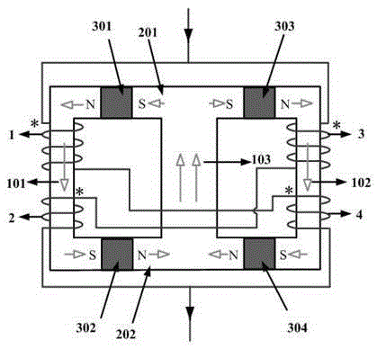
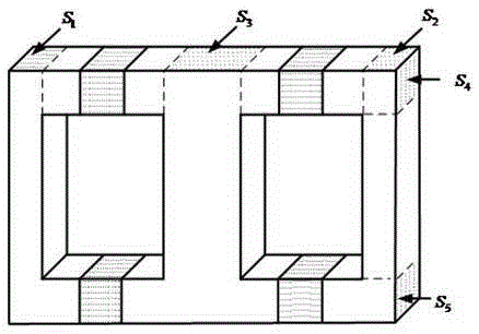
[0030] Such as figure 1As shown, a parallel magnetic saturation fault current limiter based on rare earth permanent magnet materials, hereinafter referred to as a fault current limiter, includes a magnetic core and a coil winding. The magnetic core includes a central column 103 and is located on both sides of the central column 103 The left column 101 and the right column 102, the upper and lower ends of the middle column 103 respectively have an upper yoke 201 and a lower yoke 202, and the upper yoke 201 is embedded with a first permanent magnet 301 and a third permanent magnet 303 , the second permanent magnet 302 and the fourth permanent magnet 304 are i...


PUM


Abstract

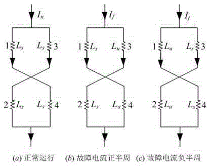
The invention discloses a parallel magnetic saturation fault current limiter based on a rare earth permanent magnet material. The fault current limiter comprises a magnetic core and a coil winding. The magnetic core comprises a middle column, and a left column and a right column located on the two sides of the middle column respectively. The upper and lower ends of the middle column are respectively equipped with an upper transverse yoke and a lower transverse yoke. A first permanent magnet and a third permanent magnet are embedded into the upper transverse yoke. A second permanent magnet and a fourth permanent magnet are embedded into the lower transverse yoke. The two ends of the upper transverse yoke and the lower transverse yoke are connected with the left column and the right column respectively, and the middle parts are connected with the middle column. The coil winding comprises a first coil and a second coil wound on the left column, and a third coil and a fourth coil wound on the right column. The dotted terminals of the first coil and the third coil are connected in parallel, the unlike terminals of the first coil and the fourth coil are connected in series, the unlike terminals of the third coil and the second coil are connected in series, and the dotted terminals of the second coil and the fourth coil are connected in parallel. The permanent magnet technology and the magnetically-controlled reactor technology are combined to limit the short-circuit fault current, and the current limiting effect is good. The fault current limiter is of high reliability and low cost.

Description

technical field [0001] The invention belongs to the technical field of high-voltage electrical equipment, and relates to a device for limiting the fault current of an AC transmission network, in particular to a parallel magnetic saturation fault current limiter based on rare earth permanent magnet materials. Background technique [0002] With the rapid and sustainable development of my country's economy, the demand for electricity continues to increase, and the scale of the power system is also increasing. The continuous increase of the power grid capacity of the power system brings with it the continuous increase of the short-circuit current level in the system, and the partial short-circuit fault current level even exceeds the breaking capacity of the circuit breaker, and the upward trend is becoming more and more obvious, which seriously threatens the power system. Safe and stable operation. At present, the main measures to limit the short-circuit current level of the po...

Claims


Application Information

Patent Timeline
Patent Type & Authority Applications(China)
IPC IPC(8): H02H9/02
CPCH02H9/021
Inventor 袁佳歆雷洋钟永恒陈柏超田翠华
Owner WUHAN UNIV
Learn More