Dismountable locking mechanism of drawer slide rail and side plate
A locking mechanism and side plate technology, which is applied in the direction of drawers, thin plate connections, connecting components, etc., can solve the problems of complex locking adjustment mechanism structure, increasing drawer load capacity, cumbersome disassembly and assembly procedures, etc., to achieve fast disassembly and assembly, high performance Reliable, low manufacturing and maintenance costs
- Summary
- Abstract
- Description
- Claims
- Application Information
AI Technical Summary
Problems solved by technology
Method used
Image
Examples
no. 1 example
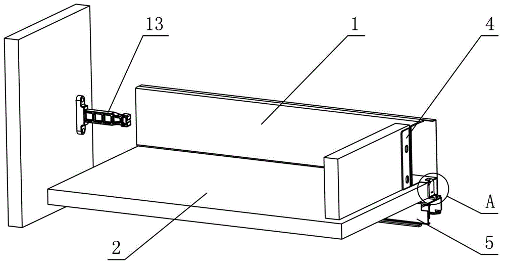
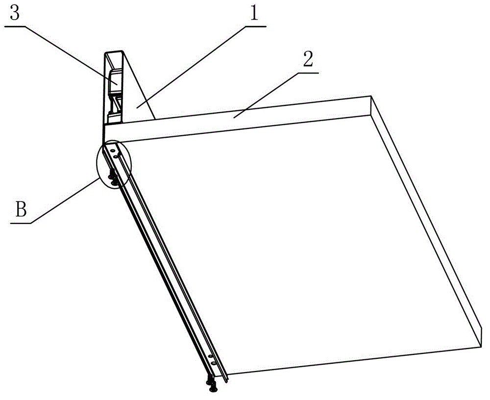
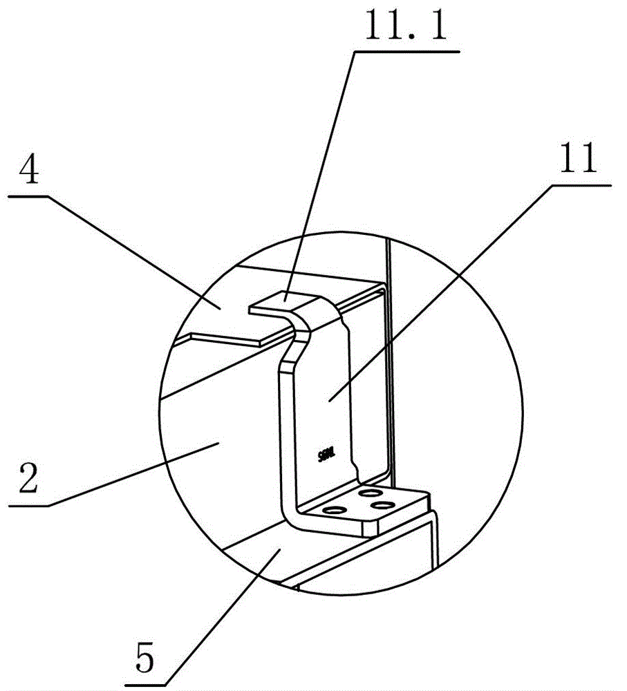
[0031] see Figure 1-Figure 14 , the detachable locking mechanism of the drawer slide rail and the side plate, including the side plate 1, the bottom plate 2 and the slide rail assembly for opening and closing the drawer, the side plate 1 is provided with the front connecting piece 3 connected to the front panel, connected The rear connector 4 of the back panel is characterized in that the side plate 1 is provided with a slot 1.1 for accommodating the bottom plate 2, and the bottom plate 2 is arranged on the slot 1.1, and acts on the moving slide rail 5 of the slide rail assembly, and the side The inner wall of the plate 1 is at least partly vertical, and transitions with the slot 1.1 at right angles, chamfers, arcs or a combination thereof; a detachable locking mechanism is provided between the side plate 1 and the movable slide rail 5, and the movable slide rail 5 It is detachably connected with the side plate 1 through a locking mechanism.
[0032] The locking mechanism is...
no. 2 example
[0039] see Figure 15 , Figure 16 , the detachable locking mechanism of the drawer slide rail and the side panel is different from the first example in that: the locking bolt 7 is provided with a convex pin 7.6 or a concave part; the lock piece 6 is provided with a pillar 6.7, and through The pillar 6.7 is rotatably connected with a lever 12, and the middle part of the lever 12 is provided with a positioning hole 12.1 corresponding to the pillar 6.7. Or the convex part is matched and connected, and the other end is provided with a boss 12.3. When the user needs to disassemble the locking mechanism, he only needs to turn the boss 12.3 on the lever 12 to drive the lock tongue 7 to slide into the cavity 6.3, then the locking mechanism and the moving slide rail 5 can be separated, and the adjustment lock can be saved through the lever principle. The force of the tongue 7 is strong in practicability.
[0040] In this embodiment, the elastic member 8 can be replaced by a torsion...
PUM
 Abstract
Description
Claims
Application Information
 - R&D
- Intellectual Property
- Life Sciences
- Materials
- Tech Scout
- Unparalleled Data Quality
- Higher Quality Content
- 60% Fewer Hallucinations
Browse by: Latest US Patents, China's latest patents, Technical Efficacy Thesaurus, Application Domain, Technology Topic, Popular Technical Reports.
© 2025 PatSnap. All rights reserved.Legal|Privacy policy|Modern Slavery Act Transparency Statement|Sitemap|About US| Contact US: help@patsnap.com


