Combined type suction cup

A combined, suction cup technology, applied in suction cups, connecting components, membrane boxes, etc., can solve problems such as reasonable allocation of unfavorable resources, increase work costs, reduce work efficiency, etc., to achieve reasonable allocation, improve work efficiency, reduce The effect of space utilization

Pending Publication Date: 2018-01-19
YAMILA AUTOMATION TECH (SUZHOU) CO LTD
View PDF6 Cites 2 Cited by
  • Summary
  • Abstract
  • Description
  • Claims
  • Application Information

AI Technical Summary

Problems solved by technology

In different application scenarios, the requirements for the structure of the suction cup and the length of the bellows are different. At this time, in order to ensure an excellent handling effect, the staff needs to replace the suction cup as a whole, which reduces the work efficiency.
At the same time, the limitation of the scope of application of the suction cup is not conducive to the rational allocation of resources, which increases the production cost. In addition, the storage space of the suction cup needs to be reasonably allocated to ensure the work efficiency and the service life of the suction cup, which increases the work cost.

Method used


Image

  • Combined type suction cup
  • Combined type suction cup
  • Combined type suction cup

Examples


Embodiment Construction

[0024] The present invention will be further described below with reference to the accompanying drawings and specific embodiments.

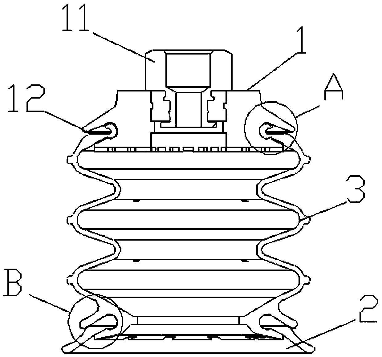
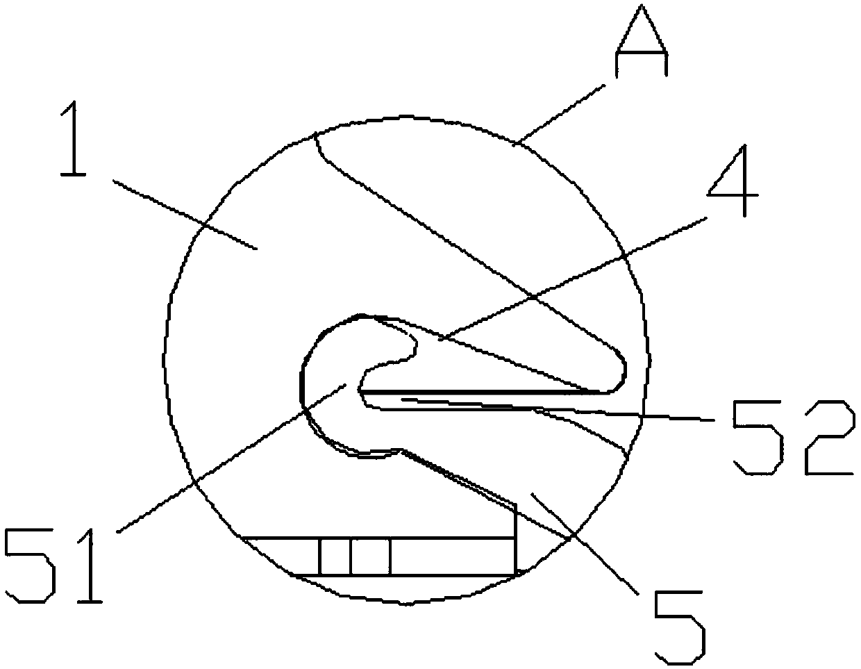
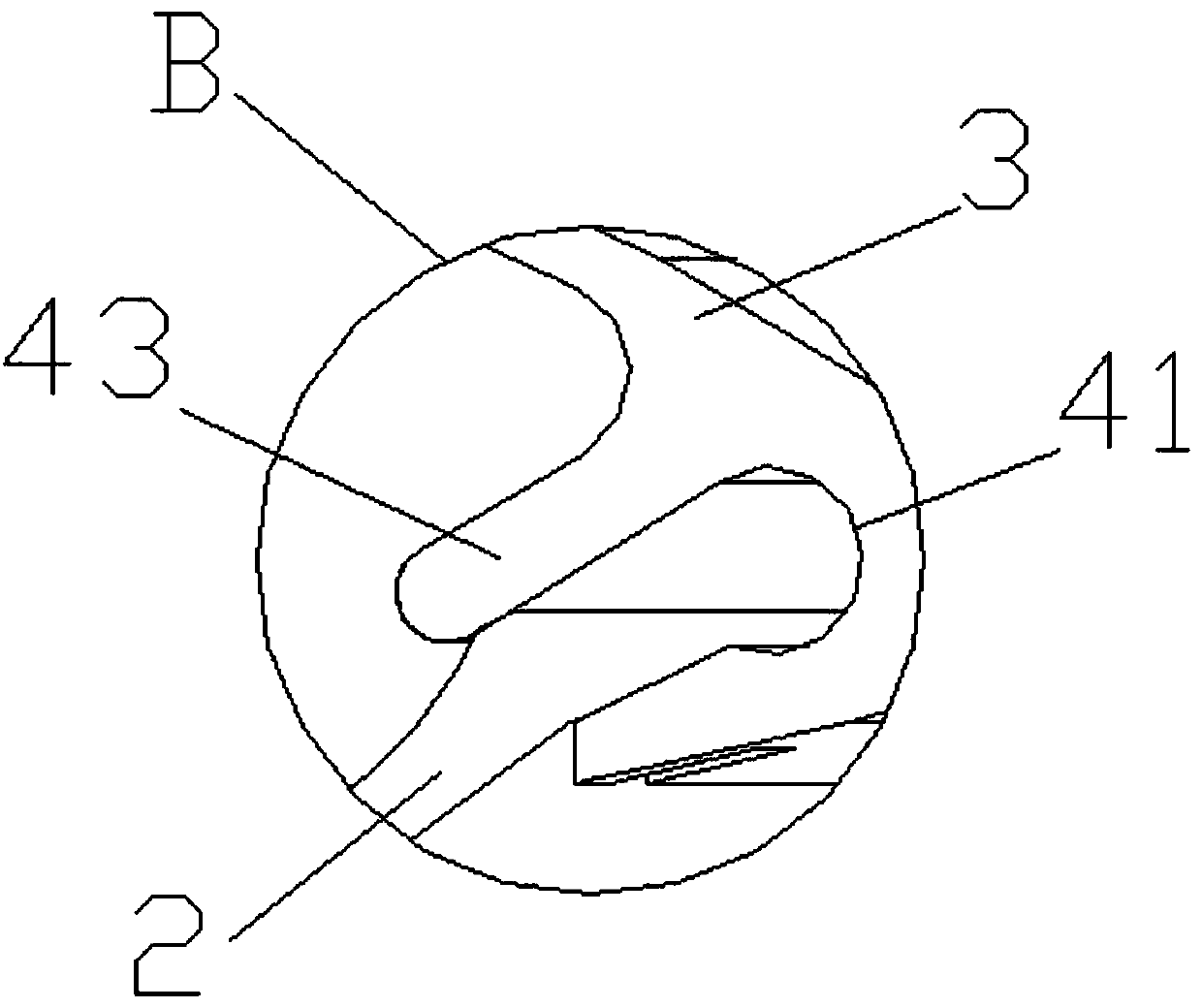
[0025] The finished connection structure of the connecting piece 1, the connecting bellows 3 and the suction cup lip 2 is as follows: Figure 4 shown. The combined suction cup is a schematic diagram of the connection between the connecting piece 1 and a connecting bellows 3 . Its internal structure is figure 1 As shown, the working end 11 of the connecting piece 1 is connected with the vacuum equipment, and the connecting end 12 at the other end of the connecting piece 1 is provided with a circumferential snap groove 4 . The clamping groove 4 located in the connector 1 can directly realize the close clamping connection with the suction cup lip 2 to form a straight vacuum suction cup structure used in daily life. The combined suction cup provided by the present invention realizes the connection operation between the connecting piece 1 and the s...


PUM


Abstract

The invention discloses a combined type suction cup used in the field of vacuum suction cups. The combined type suction cup is structurally comprises a connecting piece, an suction cup lip side and aplurality of connecting corrugated pipes, wherein the connecting piece comprises a working end and a connecting end which are connected with vacuum equipment; clamping grooves used for being connectedwith the suction cup lip are circumferentially formed in the connecting end, a clamping protruding edge which is matched with the corresponding clamping groove is arranged on one end of each connecting corrugated pipe, a clamping groove is formed in the other end of each connecting corrugated pipe, the connecting piece, the connecting corrugated pipes and the suction cup lip are sequentially andclosely clamped and connected, and a gas channel is formed in the connecting piece, the connecting corrugated pipes and the suction cup lip. According to the combined type suction cup, by structural arranging of the connecting corrugated pipes in the combined suction cup, overall frequent changing of the suction cup during operating and using is avoided, working efficiency is improved, using flexibility of the suction cup is expanded effectively, so that the application range of the suction cup can be expanded extremely, the reasonable utilizing rate of the suction cup is guaranteed, meanwhile, the storage space required by the suction cup is reduced, and reasonable allocation of resources is realized effectively.

Description

technical field [0001] The invention relates to a combined suction cup used in the field of vacuum suction cups. Background technique [0002] The vacuum suction cup is one of the vacuum equipment actuators. The vacuum suction cup is connected to the vacuum equipment through the nozzle, and then contacts with the object to be lifted such as glass, paper, etc., and starts the suction of the vacuum equipment, so that negative air pressure is generated in the suction cup, so that the object to be lifted can be sucked firmly, and then the object to be lifted can be transported. . When the object to be lifted is transported to the destination, it is smoothly inflated into the vacuum suction cup, so that the negative air pressure in the vacuum suction cup becomes zero air pressure or slightly positive air pressure, and the vacuum suction cup is separated from the object to be lifted, thus completing the lifting and conveying of heavy objects. task. [0003] There are various ty...

Claims


Application Information

Patent Timeline
Patent Type & Authority Applications(China)
IPC IPC(8): F16B47/00F16J3/04
Inventor 嵇学艳
Owner YAMILA AUTOMATION TECH (SUZHOU) CO LTD
Why Eureka
Try Eureka