Target graphic code identification method and device
A recognition method and a technology of a recognition device, which are applied in the computer field, can solve problems such as inconsistencies, and achieve the effect of improving recognition efficiency
- Summary
- Abstract
- Description
- Claims
- Application Information
AI Technical Summary
Problems solved by technology
Method used
Image

Examples
Embodiment 1
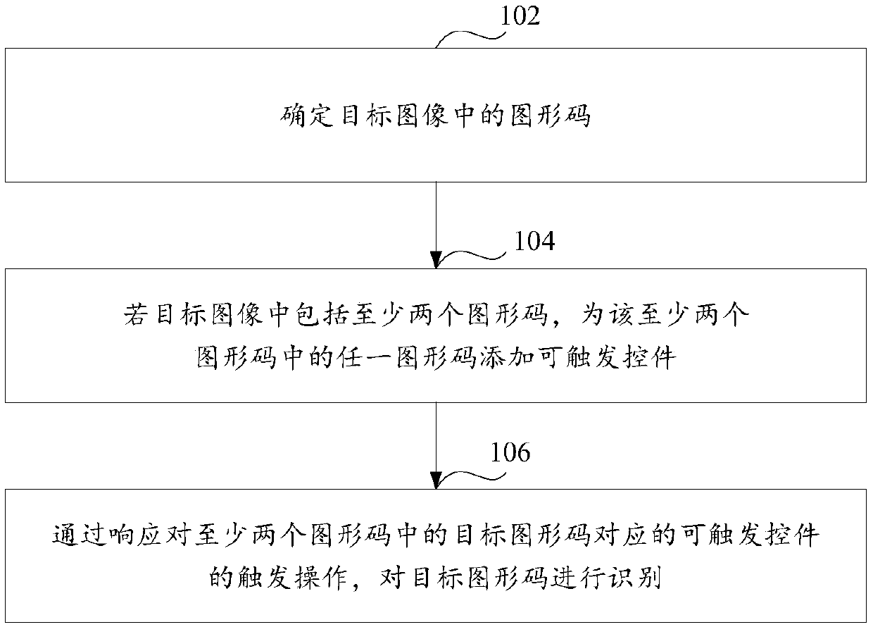
[0057] figure 1 It is a schematic flowchart of a target pattern code recognition method provided in the embodiment of the present application. The method can be as follows.
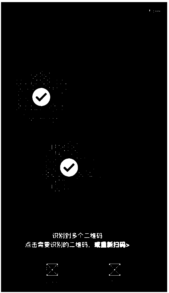
[0058] Step 102: Determine the graphic code in the target image.
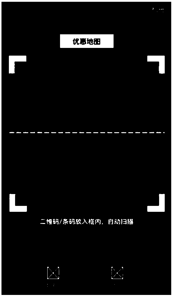
[0059] Wherein, the target image is an image in the graphic code recognition area.
[0060] In the embodiment of the present application, determining the graphic code in the target image includes:
[0061] Determine the graphic code in the target image through graphic code scanning or AR scanning.
[0062]In the embodiment of the present application, the graphic code includes at least one of the following: a barcode, a two-dimensional code, and an AR identification code.
[0063] When the user needs to identify the graphic code to obtain the data information contained in the graphic code, the user can trigger the code scanning function in the terminal device, for example, click the scan function control in the terminal device to open t...
Embodiment 2
[0095] Based on the same inventive idea, Figure 5 It is a schematic flowchart of a target pattern code recognition method provided in the embodiment of the present application. The method can be as follows.
[0096] Step 502: Determine the graphic code in the target image.
[0097] Wherein, the target image is an image in the graphic code recognition area.
[0098] In the embodiment of the present application, determining the graphic code in the target image includes:
[0099] Determine the graphic code in the target image through graphic code scanning or AR scanning.
[0100] In the embodiment of the present application, the graphic code includes at least one of the following: a barcode, a two-dimensional code, and an AR identification code.
[0101] When the user needs to identify the graphic code to obtain the data information contained in the graphic code, the user can trigger the code scanning function in the terminal device, for example, click the scan function cont...
Embodiment 3
[0136] Based on the inventive concept of the present application described in detail in the foregoing embodiment 1 and / or embodiment 2, in order to facilitate a better understanding of the technical characteristics, means and effects of the present application, the target pattern code recognition method of the present application will be further described below, thereby Form yet another embodiment of the present application.
[0137] The target pattern code recognition process in embodiment 3 of the present application is similar to the target pattern code recognition process in embodiment 1 and / or embodiment 2, other steps that are not introduced in embodiment 3 can refer to embodiment 1 and / or embodiment The relevant description in 2 will not be repeated here.
[0138] Before the implementation of the solution is introduced in detail, the implementation scenario of the solution is briefly introduced.
[0139] This implementation scenario is the scenario of scanning code pay...
PUM
 Abstract
Description
Claims
Application Information
 - Generate Ideas
- Intellectual Property
- Life Sciences
- Materials
- Tech Scout
- Unparalleled Data Quality
- Higher Quality Content
- 60% Fewer Hallucinations
Browse by: Latest US Patents, China's latest patents, Technical Efficacy Thesaurus, Application Domain, Technology Topic, Popular Technical Reports.
© 2025 PatSnap. All rights reserved.Legal|Privacy policy|Modern Slavery Act Transparency Statement|Sitemap|About US| Contact US: help@patsnap.com