Micro switch with heat dissipation structure

A technology of micro switch and heat dissipation structure, which is applied in the direction of electric switches, electrical components, circuits, etc., and can solve the problem of affecting the reliability of the connection between the conduction contact rod and the incoming terminal and outgoing terminal, affecting the normal function and applicability of the micro switch and practicability limitations, etc., to achieve the effects of arc extinguishing, improving stability and service life, and increasing the scope of application

Active Publication Date: 2020-02-11
浙江纳仕通电气有限公司
View PDF9 Cites 0 Cited by
  • Summary
  • Abstract
  • Description
  • Claims
  • Application Information

AI Technical Summary

Problems solved by technology

[0002] The micro switch is a common structure. The micro switch of the traditional technology is mainly composed of a bottom case and a cover. The bottom case is provided with an incoming terminal, an outgoing terminal and a button, and a conduction contact is arranged in the bottom case. Rod, the conduction contact rod connects the incoming line terminal and the outgoing line terminal under the action of the button, because the conduction contact rod will also generate a certain amount of heat when it is connected to the incoming line terminal and the outgoing line terminal, especially for a long time In the case of high temperature environment, the heat in the micro switch cannot be dissipated, which will affect the reliability of the connection between the internal conduction contact rod and the incoming and outgoing terminals, and affect the normal function of the micro switch, so the applicability and practicality sexually restricted

Method used


Image

  • Micro switch with heat dissipation structure
  • Micro switch with heat dissipation structure

Examples


Embodiment 1

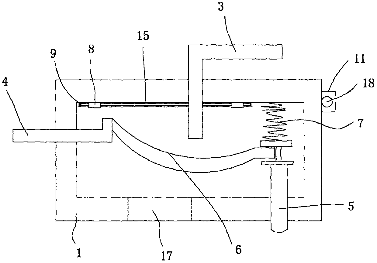
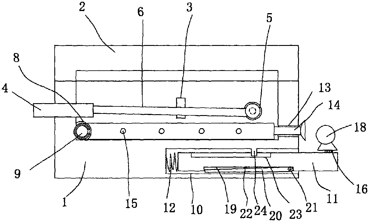
[0014] figure 1 and figure 2 A specific embodiment of the invention is shown in which figure 1 It is a structural schematic diagram of the present invention; figure 2 It is a sectional structure diagram of the present invention.

[0015] See figure 1 and figure 2 , a micro switch with a heat dissipation structure, including a bottom case 1 and a cover 2, on which the bottom case 1 is provided with an incoming line terminal 3, an outgoing line terminal 4 and a button 5, and inside the bottom case 1 is provided with Conduction contact rod 6, there is a return spring 7 between the button 5 and the inner wall of the bottom case 1, and the conduction contact rod 6 connects the incoming line terminal 3 and the outgoing line terminal 4 under the action of the button 5 conduction, a clamp 8 is provided on the inner wall of the bottom case 1, and a heat dissipation air guide pipe 9 is arranged inside the bottom case 1, and the heat dissipation air guide pipe 9 is fixed on the b...


PUM


Abstract

The invention discloses a microswitch with a heat dissipation structure. The microswitch comprises a bottom shell and a face cover, a wire inlet terminal, a wire outlet terminal and a button are arranged on the bottom shell, a connecting feeler lever is arranged inside the bottom shell, a resetting spring is arranged between the button and the inner wall of the bottom shell, clamps are arranged onthe inner wall of the bottom shell, a heat dissipation air-guiding pipe is arranged inside the bottom shell and fixed to the inner wall of the bottom shell through the clamps, a cavity with an opening in the side face is formed in the bottom shell, a bearing plate is arranged inside the cavity, a resetting tension spring is fixed between the end of the bearing plate and the end wall of the cavity, a round hole is formed in the side wall of the bottom shell, air outlet holes are evenly formed in the heat dissipation air-guiding pipe, a heat dissipation window is formed in the side wall of thebottom shell, and a small heat dissipation air blower is further arranged. The microswitch is reasonable in structural arrangement, the overall heat dissipation performance of the microswitch is greatly improved, arc extinguishing of the microswitch is easy, using stability is improved, the service life is prolonged, the application range is enlarged, and practicability is good.

Description

technical field [0001] The invention belongs to the technical field of micro switches, and in particular relates to a micro switch with a heat dissipation structure. Background technique [0002] The micro switch is a common structure. The micro switch of the traditional technology is mainly composed of a bottom case and a cover. The bottom case is provided with an incoming terminal, an outgoing terminal and a button, and a conduction contact is arranged in the bottom case. Rod, the conduction contact rod connects the incoming line terminal and the outgoing line terminal under the action of the button, because the conduction contact rod will also generate a certain amount of heat when it is connected to the incoming line terminal and the outgoing line terminal, especially for a long time In the case of high temperature environment, the heat in the micro switch cannot be dissipated, which will affect the reliability of the connection between the internal conduction contact ro...

Claims


Application Information

Patent Timeline
Patent Type & Authority Patents(China)
IPC IPC(8): H01H9/52
Inventor 孔宇灿
Owner 浙江纳仕通电气有限公司
Why Eureka
Try Eureka