High-safety power cabinet

A high-security, power cabinet technology, applied in the substation/power distribution device shell, substation/switchgear cooling/ventilation, anti-seismic equipment, etc., to achieve the effects of preventing shaking, enhancing heat dissipation, and convenient fixing

Inactive Publication Date: 2018-01-19
佛山杰致信息科技有限公司
View PDF4 Cites 15 Cited by
  • Summary
  • Abstract
  • Description
  • Claims
  • Application Information

AI Technical Summary

Problems solved by technology

[0005] The purpose of the present invention is to solve the problem that the internal structure of the power cabinet is relatively simple in the prior art, and the problem of the lack of a monitoring and control mechanism for the internal temperature of the power cabinet is proposed, and a high-safety power cabinet is proposed.

Method used


Image

  • High-safety power cabinet
  • High-safety power cabinet
  • High-safety power cabinet

Examples


Embodiment 1

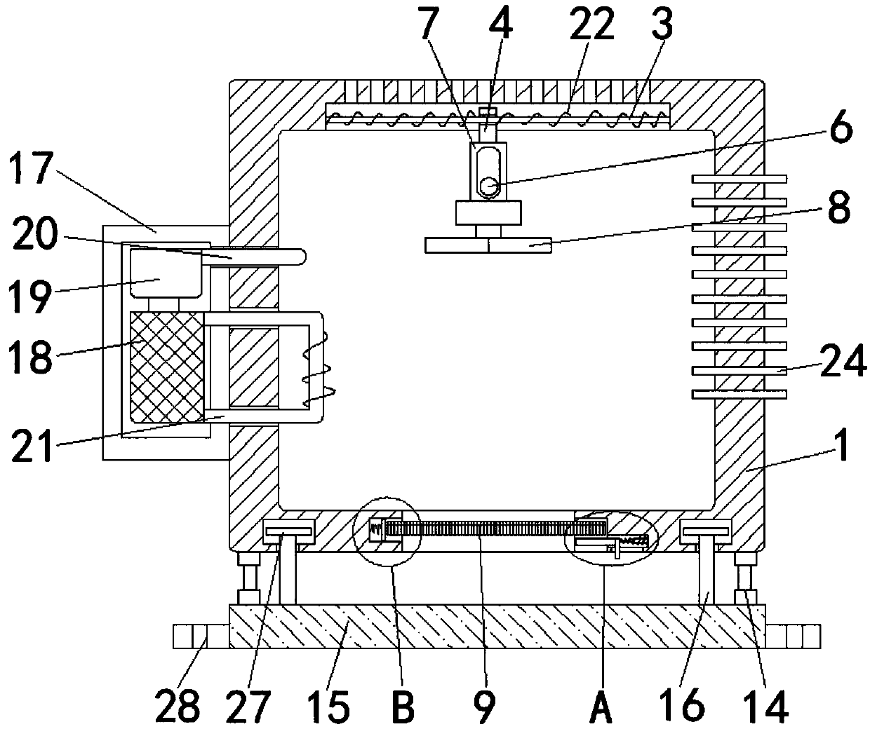
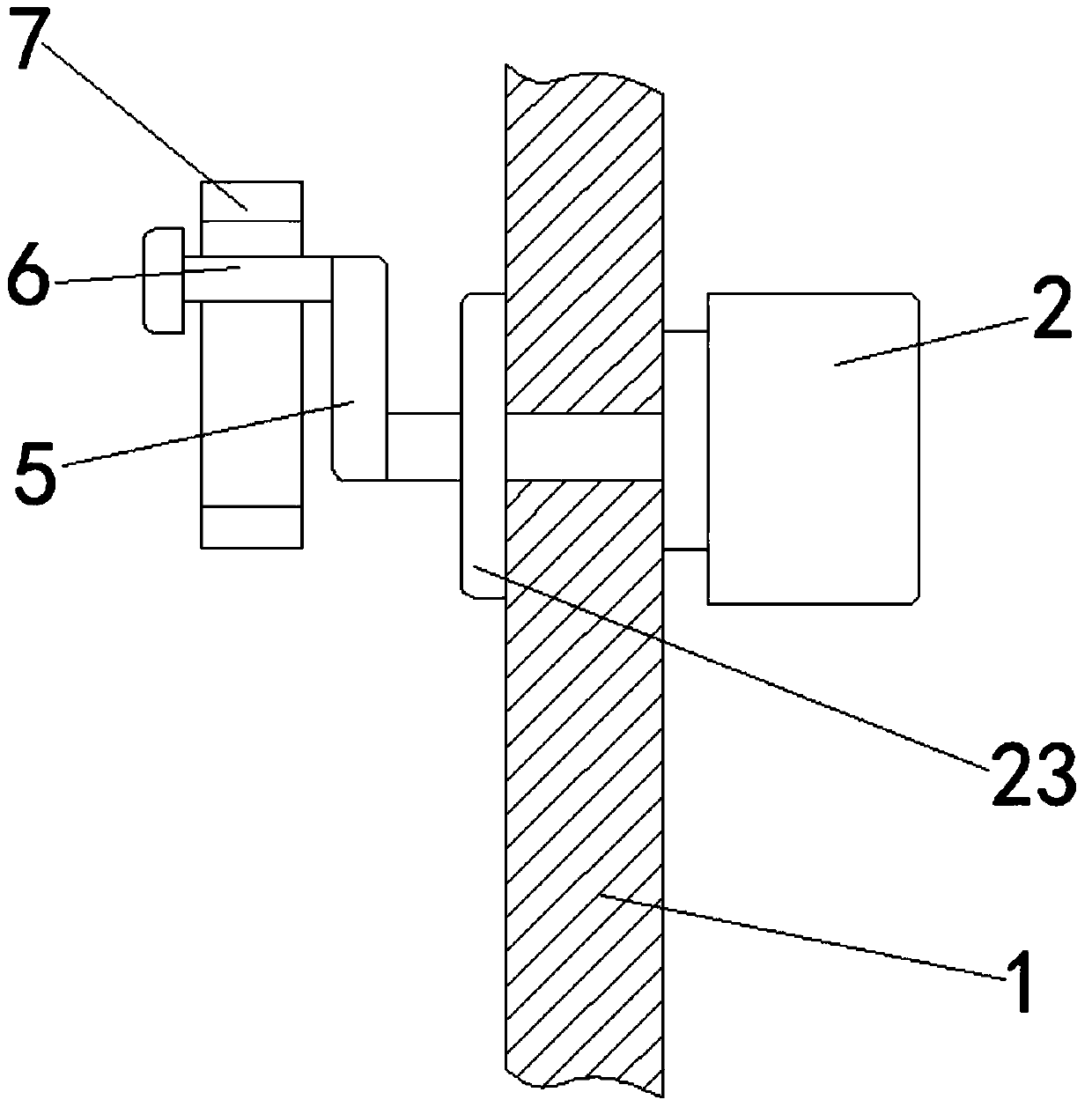
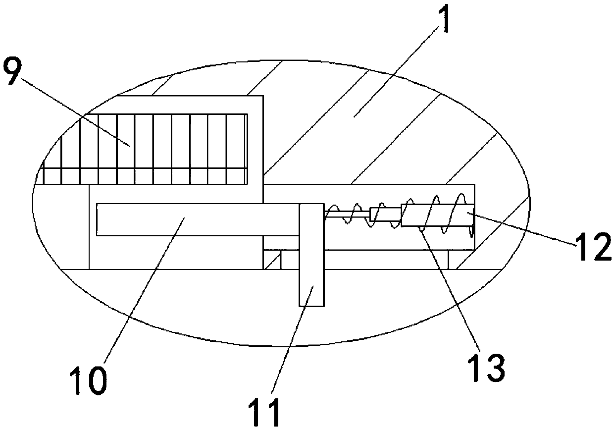
[0031] refer to Figure 1-4 , a high-safety power cabinet, including a main cabinet body 1 and a drive motor 2, the drive motor 2 is fixedly connected to one side of the outer wall of the main cabinet body 1, and the inner top of the main cabinet body 1 is provided with a chute for setting The slide bar 3 is fixedly connected with the slide bar 3 in the chute for supporting the slide block 4. The slide bar 3 is slidably sleeved with the slide block 4 for driving the slide sleeve 7 to move left and right. The output shaft of the drive motor 2 runs through the main shaft. The outer wall of the cabinet body 1 is fixedly connected with a rotating rod 5 for driving the shaft rod 6 to rotate. The end of the rotating rod 5 away from the output shaft of the drive motor 2 is fixedly connected with a shaft rod 6 for driving the sliding sleeve 7 to move left and right. 6. The upper sliding sleeve is connected with a sliding sleeve 7, which is used to drive the electric fan 8 to move left...


PUM


Abstract

The invention discloses a high-safety power cabinet, comprising a main cabinet body and a driving motor; the driving motor is fixedly connected to the outer wall of one side of the main cabinet body;the inner top of the main cabinet body is provided with a slide channel, a slide rod is fixedly connected inside the slide channel, the slide rod is slidably sleeved with a slide block, an output shaft of the driving motor runs through the outer wall of the main cabinet body and is fixedly connected with a rotary rod, one end of the rotary rod far away from the output shaft of the driving motor isfixedly connected with a shaft rod, the shaft rod is slidably sleeved with a slide sleeve, the top of the slide sleeve is fixedly connected with the slide block, an electric fan is fixedly connectedto the bottom of the slide sleeve, the inner bottom of the main cabinet is provided with an air vent corresponding to the electric fan, and a dustproof mesh is slidably inserted in the air vent. As control mechanisms are arranged in separated positions herein, interior temperature of the power cabinet can be monitored and controlled, thereby preventing too high or too low interior temperature of the main cabinet body from affecting normal operation of electrical components.

Description

technical field [0001] The invention relates to the technical field of power distribution equipment, in particular to a high-safety power cabinet. Background technique [0002] The power cabinet is the final equipment of the power distribution system. The power cabinet is the general name of the motor control center. The electric energy of a certain channel of the upper-level power distribution equipment is distributed to the nearby loads, and this level of equipment should provide protection, monitoring and control for the loads. [0003] However, the internal structure of the existing power cabinet is relatively simple, and there is a lack of a mechanism for monitoring and controlling the internal temperature of the power cabinet, which may easily cause the internal temperature of the power cabinet to be too high or too low, resulting in damage to electrical components, which has great defects. Needs to be improved. Contents of the invention [0004] 1. Technical probl...

Claims


Application Information

Patent Timeline
Patent Type & Authority Applications(China)
IPC IPC(8): H02B1/56H02B1/28H02B1/54H02B1/30
Inventor 王玉环
Owner 佛山杰致信息科技有限公司
Why Eureka
Try Eureka