Message processing method and device
A message processing and message technology, applied in the field of communication
- Summary
- Abstract
- Description
- Claims
- Application Information
AI Technical Summary
Problems solved by technology
Method used
Image

Examples
Embodiment Construction
[0094] The embodiments will be described in detail below in conjunction with the accompanying drawings.
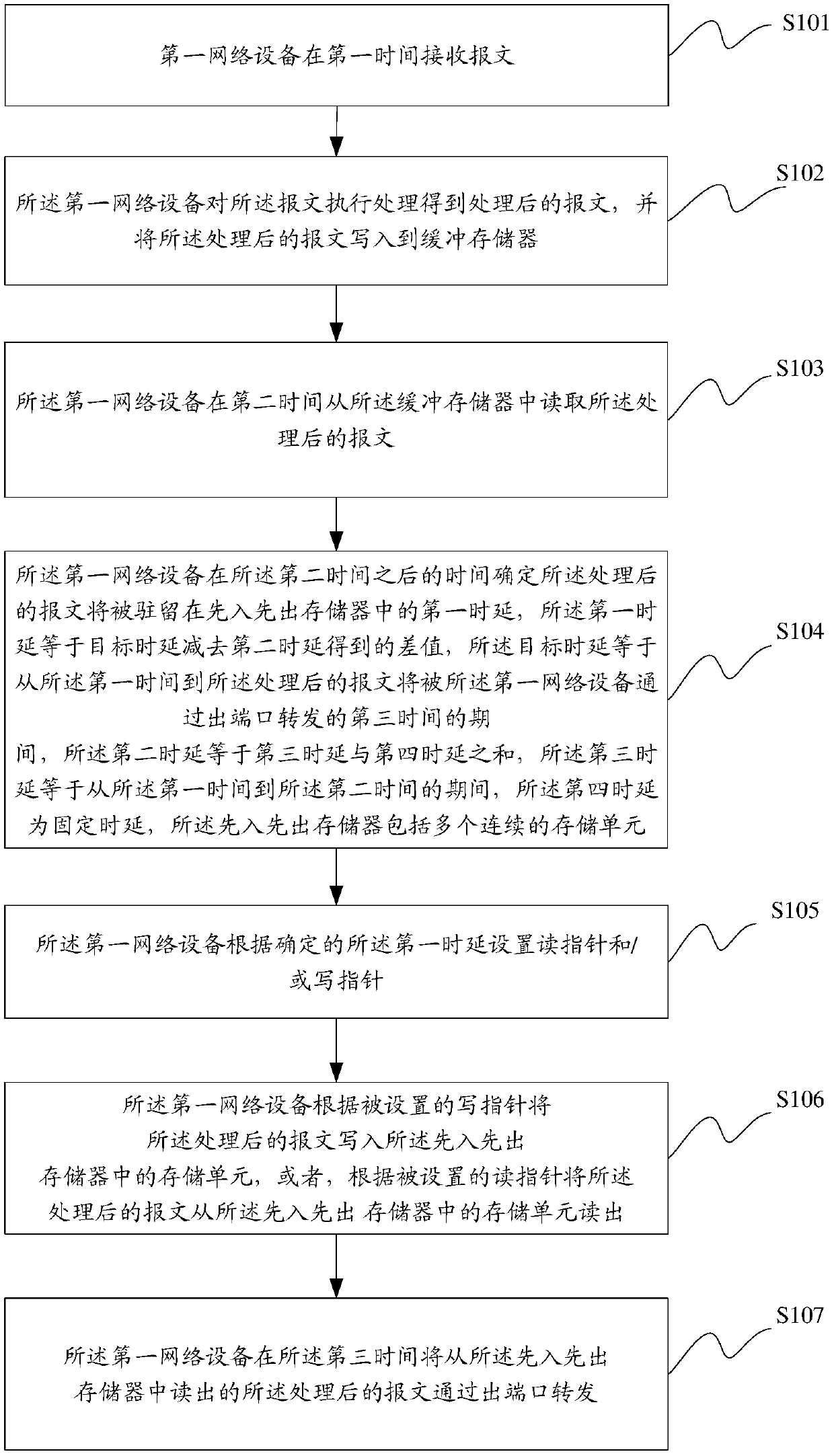
[0095] Such as figure 1 As shown, a schematic flowchart of a method for processing a packet provided by an embodiment of the present invention includes the following steps.
[0096] S101: The first network device receives the packet at the first time.
[0097] For example, the first network device may be a PTN (Packet Transport Network, packet transport network) device, an OTN (Optical Transport Network, optical transport network) device, a router, or a switch.
[0098] In the embodiment of the present invention, the first time is the time when the first network device receives the packet.
[0099]For example, the service carried by the packet may be a CPRI service, an SDH service or a PDH service.
[0100] For example, when the first network device receives the packet at the first time, it may record the first time at which the packet is received.
[0101] For example...
PUM
 Abstract
Description
Claims
Application Information
PatSnap Eureka turns technology decisions into work you can execute. Powered by our Innovation Knowledge Graph, it runs expert workflows across engineering, life sciences, materials and intellectual property. Get your review-ready output in minutes.


