
Laser marking coding method based on visual sensor

A visual sensor and laser marking technology, which is applied in the field of laser marking, can solve the problems of no steps to detect whether the marking information is correct or not, and low detection efficiency, so as to reduce the probability of misjudgment by naked eyes and improve accuracy. rate, the effect of improving efficiency

Inactive Publication Date: 2018-01-23
田喜桂
View PDF0 Cites 1 Cited by
  • Summary
  • Abstract
  • Description
  • Claims
  • Application Information

AI Technical Summary

Problems solved by technology

[0004] The present invention solves the problems in the prior art that there is no step to detect whether the coding and marking information is correct or not, the detection requires relevant personnel and the detection efficiency is low, and provides a laser marking and coding method based on a visual sensor, which only needs to be applied when it is applied. One person is required to complete the work of marking and testing. You can mark or code on the device. After marking or coding is completed, the device will immediately use visual inspection to verify whether the mark or code is correct.

Method used


Image

  • Laser marking coding method based on visual sensor

Examples


Embodiment

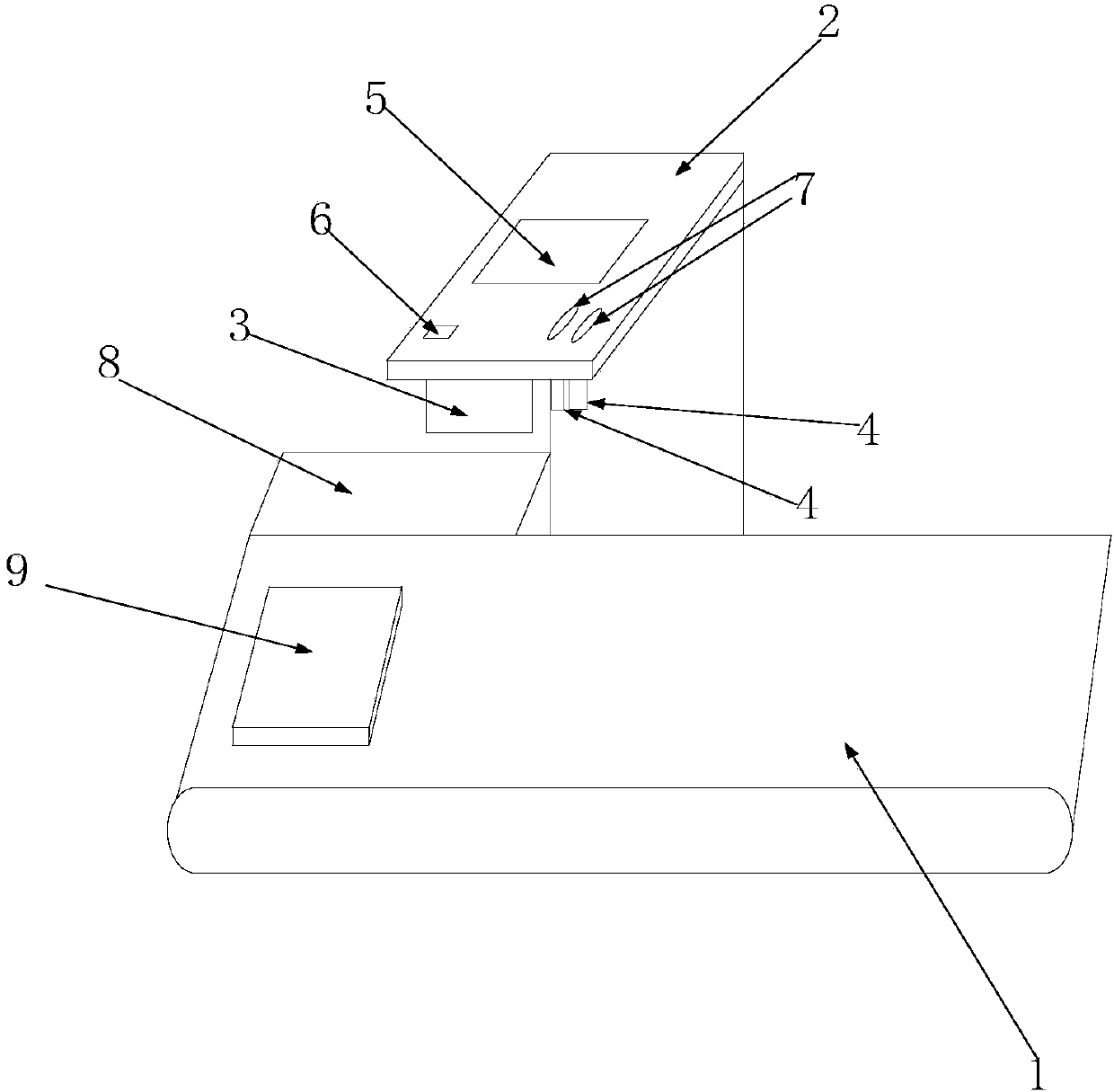
[0027] Such as figure 1 As shown, the laser marking and coding method based on the visual sensor, the following steps are performed in sequence:

[0028] A: Put the product on the conveyor belt and move from left to right under the drive of the conveyor belt;

[0029] B: The laser generator marks the set label or barcode on the surface of the product;

[0030] C: When the products with labels or barcodes continue to be delivered to the vision sensor, the vision sensor collects the visual information of the product and transmits it to the control component;


PUM


Abstract

The invention discloses a laser marking coding method based on a visual sensor. A worktable is included, a conveying belt and a control assembly are arranged on the worktable, a support table is arranged above the conveying belt, a laser generator and the visual sensor are sequentially arranged below the support table in the conveying direction of the conveying belt, a display assembly is arrangedabove the support table, and the laser generator, the visual sensor, the display assembly and the conveying belt are connected with the control assembly. The problems that in the prior art, the stepof whether coding marking information is detected to be correct or not does not exist, related persons need to be prepared during detection, and the detection efficiency is low are solved, through thelaser marking coding method based on the visual sensor, during application, only one person can finish coding and detection work, marking or coding on the equipment is achieved, and after marking orcoding is finished, whether marking or coding is correct or not is verified through the visual detection manner.

Description

technical field [0001] The invention relates to laser marking, in particular to a visual sensor-based laser marking and coding method. Background technique [0002] Laser marking is a technology widely used in industrial production. It is mainly used to print some basic information on product casings or panels made of paper, plastic or metal. It is directly vaporized at high temperature on the surface of the object by laser, and can be distinguished by naked eyes without any auxiliary tools, which is convenient for consumers to identify. For example, use laser coding and marking on the outer packaging of the product or the shell of the plastic and metal product to engrave the product model, trademark or production date and other information. In the process of laser marking and coding, the working state of the laser marking and marking machine is unstable or the marking product to be marked moves during the transportation process, which leads to the inability of the laser m...

Claims


Application Information

Patent Timeline
Patent Type & Authority Applications(China)
IPC IPC(8): B41M5/24
Inventor 田喜桂
Owner 田喜桂
Learn More