Environment-friendly garbage incineration equipment

An environmentally friendly and equipment technology, applied in lighting and heating equipment, incinerators, combustion methods, etc., can solve the problems of harmful gas production, environmental pollution, low incineration efficiency, etc., to achieve the effect of ensuring cleanliness

Inactive Publication Date: 2018-01-23
曹茂娟
0 Cites 11 Cited by

AI-Extracted Technical Summary

Problems solved by technology

[0003] With the development of society and the increase of population, more and more garbage is produced in society, and more and more people pay more and more attention to the disposal of garbage. Nowadays, many garbage that cannot be recycled and reused are often incinerated by incinerators. The heat gene...

Method used

Described incinerator 4 upper side left and right ends are provided with smoke exhaust pipe 16, described smoke exhaust pipe 16 inside is provided with dividing plate 17, and described dividing plate 17 upper and lower both sides outer ends are provided with air vent 18, so A filter cavity 19 is provided on the outside of the air vent 18, and installation grooves 20 are arranged at the left and right ends of the inside of the filter cavity 19, and a filter screen 21 is arranged between the installation grooves 20, which can effectively filter the smoke and dust discharged, so that It can effectively prevent the dust from polluting the environment. The filter screen 21 is provided with a vibrator, which can effectively vibrate the dust adhered on the filter screen 21 to the bottom of the filter cavity 19. The filter screen 21 is installed with the Springs 22 are arranged on the upper and lower sides between the grooves 20, while ensuring the vibration of the filter screen 19, the vibration to the equipment can be reduced. The lower side of the filter chamber 19 is provided with a dust discharge pipe 23, and the dust discharge pipe 23 is provided with a control valve, which can facilitate the processing of collected dust, and the upper side of the partition 17 is provided with an activated carbon adsorption layer 24, which can effectively absorb harmful gases in the smoke and dust, so that the cleanness of the discharged gas can be guaranteed.
Referring to Fig. 1~3, in the embodiment of the present invention, a kind of environment-friendly waste incineration equipment, comprises base plate 1, and described base plate 1 lower side four corners are provided with support base 2, and described support base 2 internal lower side is provided with The friction pad can effectively increase the friction between the equipment and the ground, which can effectively ensure the stability of the equipment. The four corners of the upper side of the bottom plate 1 are provided with support columns 3, and the upper side of the support column 3 is provided with a combustion furnace 4 , the left and right sides of the lower end of the combustion furnace 4 are equipped with deflectors, which can facilitate the discharge of impurities produced after garbage combustion, and the middle part of the right side of the combustion furnace 4 is provided with an electric control box 5, which can effectively control the operation of the equipment and work, the middle part of the lower side of the combustion furnace 4 is provided with an ash discharge pipe 6, and the ash discharge pipe 6 is provided with a solenoid valve, and the inner lower end of the combustion furnace 4 is provided with a fire grate 7, and the upper side of the fire grate 7 The right en...

Abstract

The invention discloses environment-friendly garbage incineration equipment. The environment-friendly garbage incineration equipment comprises a bottom plate, supporting columns are arranged at the four corners of the upper side of the bottom plate, an incineration furnace is arranged on the upper sides of the supporting columns, an electric control cabinet is arranged on the right side of the incineration furnace, and a furnace rate is arranged at the lower end of the interior of the incineration furnace. An igniter is arranged at the right end of the upper side of the furnace grate, an air inlet pipe is arranged at the left end of the lower side of the furnace grate, a smashing cavity is formed in the left side of the incineration furnace, and smoke exhausting pipes are arranged at the left end and the right end of the upper side of the incineration furnace. A separation plate is arranged in each of the smoke exhausting pipe, air vents are formed in the outer ends of the upper side and the lower side of each separation plate, and a filtering cavity is formed in the outer side of each air vent. A mounting groove is formed in each filtering cavity, a filtering screen is arranged between the mounting grooves, an active carbon adsorption layer is arranged on the upper side of each separation plate, a supporting pipe is arranged between the smoke exhausting pipes, a second motor is arranged at the top end of the interior of the supporting pipe, and a screw rod is arranged on the lower side of the second motor. A telescopic rod is arranged on the outer side of the lower end ofthe screw rod, connection rods are arranged on the left side and the right side of the lower end of the telescopic rod correspondingly, and a scraping ring is arranged on the outer side of each connection rod. The environment-friendly garbage incineration equipment can effectively improve the incineration efficiency, and cleaning of the interior of the incineration furnace after incineration is facilitated.

Application Domain

Technology Topic

Image

  • Environment-friendly garbage incineration equipment
  • Environment-friendly garbage incineration equipment
  • Environment-friendly garbage incineration equipment

Examples

  • Experimental program(1)

Example Embodiment

[0017] It should be noted that the embodiments of the present invention and the features in the embodiments can be combined with each other if there is no conflict.
[0018] In the description of the present invention, it should be understood that the terms "center", "longitudinal", "transverse", "upper", "lower", "front", "rear", "left", "right", " The orientation or positional relationship indicated by "vertical", "horizontal", "top", "bottom", "inner", "outer" etc. is based on the orientation or positional relationship shown in the drawings, and is only for the convenience of describing the present invention and The description is simplified, rather than indicating or implying that the pointed device or element must have a specific orientation, be constructed and operated in a specific orientation, and therefore cannot be understood as a limitation of the present invention. In addition, the terms "first", "second", etc. are only used for descriptive purposes, and cannot be understood as indicating or implying relative importance or implicitly indicating the number of indicated technical features. Therefore, the features defined with "first", "second", etc. may explicitly or implicitly include one or more of these features. In the description of the present invention, unless otherwise specified, "plurality" means two or more.
[0019] In the description of the present invention, it should be noted that the terms "installation", "connected" and "connected" should be understood in a broad sense, unless otherwise clearly specified and limited. For example, they can be fixed or detachable. Connected or integrally connected; it can be a mechanical connection or an electrical connection; it can be directly connected or indirectly connected through an intermediate medium, and it can be the internal communication between two components. For those of ordinary skill in the art, the specific meaning of the above-mentioned terms in the present invention can be understood through specific situations.
[0020] Hereinafter, the present invention will be described in detail with reference to the drawings and in conjunction with the embodiments.
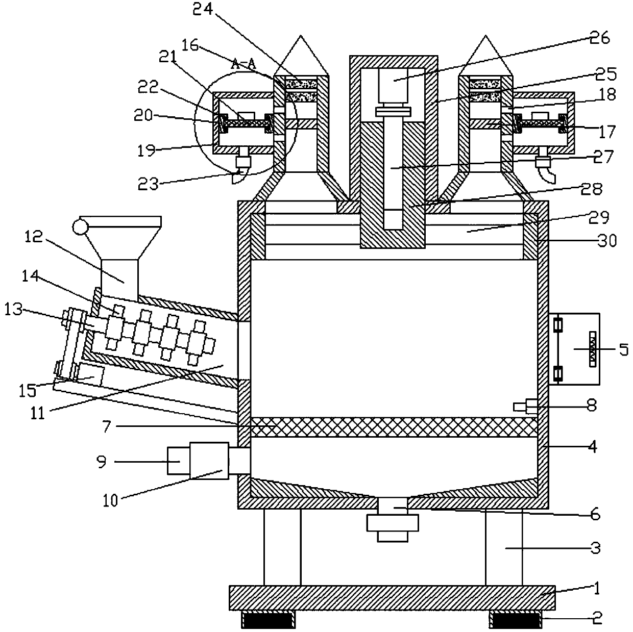
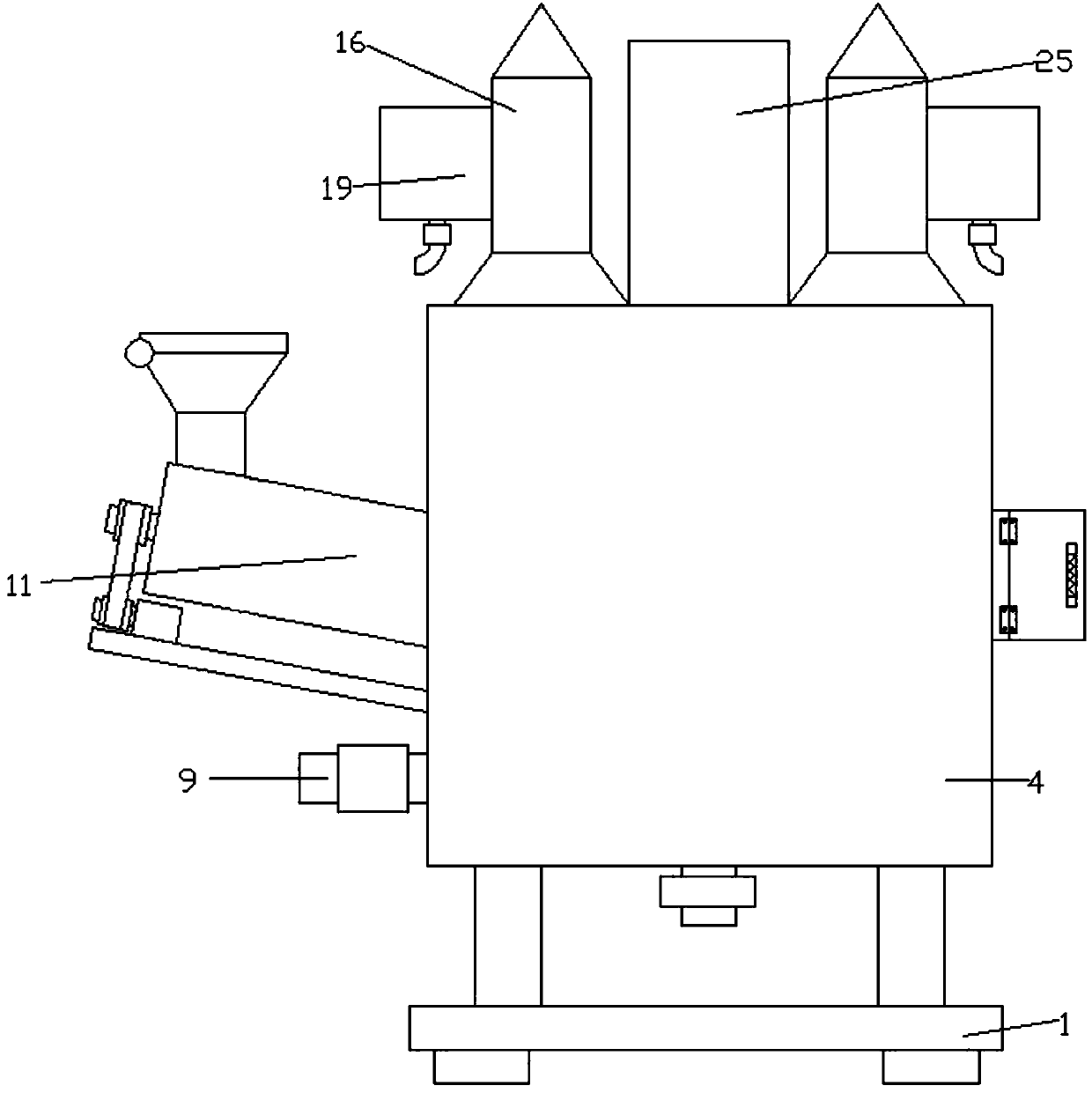
[0021] Refer to Figure 1~3 In the embodiment of the present invention, an environmentally friendly waste incineration equipment includes a bottom plate 1. The bottom plate 1 is provided with support seats 2 on the four corners of the bottom, and friction pads are provided on the lower side of the support seat 2, which can effectively increase equipment The friction force between the ground and the ground can effectively ensure the stability of the equipment. The four corners of the bottom plate 1 are provided with support columns 3, and the upper side of the support columns 3 are provided with a combustion furnace 4, and the internal lower end of the combustion furnace 4 There are baffles on the left and right sides to facilitate the discharge of impurities generated after the burning of garbage. The middle of the right side of the combustion furnace 4 is provided with an electric control box 5, which can effectively control the operation and work of the equipment. An ash outlet pipe 6 is provided in the middle of the lower side, the ash outlet pipe 6 is provided with a solenoid valve, the inner lower end of the combustion furnace 4 is provided with a grate 7 and the upper right end of the grate 7 is provided with an igniter 8. The lower left end of the grate 7 is provided with an air inlet pipe 9, and the air inlet pipe 9 is provided with a fan 10. During the combustion process of the combustion furnace 4, the fan 10 can effectively provide oxygen to the inside, thus ensuring the equipment Burning.
[0022] The left side of the combustion furnace 4 is provided with a crushing chamber 11, the upper left end of the crushing chamber 11 is provided with a feeding port 12, and the upper side of the feeding port 12 is provided with a sealing cover, which can effectively ensure the sealing of the equipment. A crushing shaft 13 is provided inside the cavity 11, and crushing blades 14 are provided on the upper and lower sides of the crushing shaft 13, a first motor 15 is provided on the lower side of the crushing cavity 12, and a mounting plate is provided on the lower side of the first motor 15; The first motor 15 can be effectively and conveniently fixed and installed. The first motor 15 is connected to the crushing shaft 13 through a belt, and the crushing shaft 13 is driven to rotate by the first motor 15, so that the crushing blade 14 crushes the garbage, which can effectively Improve waste incineration efficiency and incineration effect.
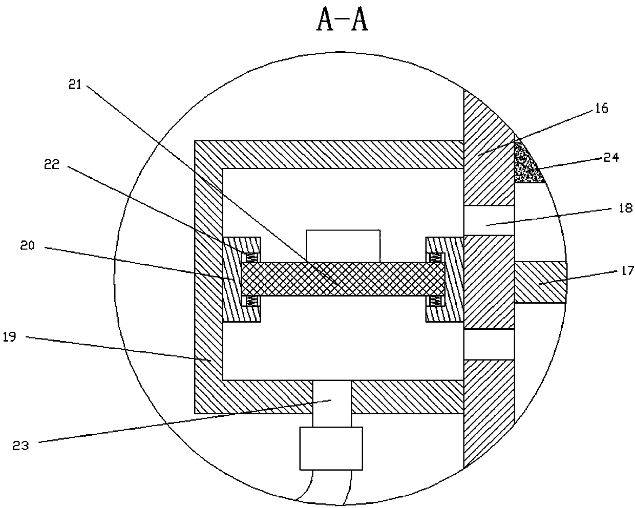
[0023] The upper and the left and right ends of the incinerator 4 are provided with smoke exhaust pipes 16, and the smoke exhaust pipe 16 is provided with partitions 17 inside, and the outer ends of the upper and lower sides of the partitions 17 are provided with vents 18, the vents 18 is provided with a filter cavity 19 on the outside. The inner left and right ends of the filter cavity 19 are provided with installation grooves 20, and a filter 21 is arranged between the installation grooves 20, which can effectively filter the exhausted smoke and dust, which can effectively To prevent dust from polluting the environment, the filter 21 is equipped with a vibrator, through which the dust adhering to the filter 21 can be effectively shaken to the bottom of the filter cavity 19, and the filter 21 and the installation groove 20 are There are springs 22 on the upper and lower sides of the room to ensure the vibration of the filter 19 while reducing the vibration to the equipment. The lower side of the filter cavity 19 is provided with a dust exhaust pipe 23, and the dust exhaust pipe 23 is provided with There is a control valve, which can conveniently process the collected dust. The upper side of the partition 17 is provided with an activated carbon adsorption layer 24, which can effectively adsorb harmful gases in the smoke and dust, so as to ensure the cleanliness of the discharged gas.
[0024] A support tube 25 is provided between the exhaust pipes 16, and a second motor 26 is provided at the top end of the support tube 25. A screw rod 27 is provided on the lower side of the second motor 26. The screw rod 27 passes through a coupling The second motor 26 is connected to the second motor 26. A telescopic rod 28 is provided on the outer side of the lower end of the screw 27. The telescopic rod 28 is provided with internal threaded holes. The lower end of the telescopic rod 28 is provided with connecting rods 29 on the left and right sides. A scraper ring 30 is provided on the outside of the connecting rod 29. After the incineration is completed, the second motor 26 inside the support tube 25 drives the screw rod 27 to rotate, which drives the telescopic rod 28 to move up and down, so that the scraper ring 30 outside the telescopic rod 28 will The residual impurities on the inner wall of the incinerator 4 are scraped, so as to ensure the cleanness of the interior and increase the service life of the equipment.
[0025] In the present invention, garbage is added to the crushing cavity 11 through the feeding port 13, and then the first motor 15 is controlled by the controller inside the electric control box 5 to drive the crushing shaft 13 to rotate, so that the crushing blade 14 crushes the garbage, and the crushed garbage Enter the upper side of the grate 7 inside the incinerator 4, ignite with the igniter 9, and then control the fan 10 through the controller inside the electric control box 5 to supply air to the inside, which can effectively incinerate the garbage. The incineration process In the process, the generated smoke and dust will be discharged through the smoke exhaust pipe 16. During the sampling process, the filter inside the outer filter cavity 19 can effectively filter the dust in the smoke and dust, which can prevent the dust from polluting the air, and the activated carbon at the upper end The adsorption layer 24 can effectively adsorb harmful gases in the smoke and dust, which can ensure the cleanliness of the exhaust gas. After the incineration is completed, the controller inside the electric control box 5 controls the second motor 26 inside the support tube 25 to drive the screw 27 Rotating, this drives the telescopic rod 28 to move up and down, so that the scraper ring 30 on the outside of the telescopic rod 28 will scrape the remaining impurities on the inner wall of the incinerator 4, thus ensuring the cleanliness of the interior.
[0026] For those skilled in the art, it is obvious that the present invention is not limited to the details of the foregoing exemplary embodiments, and the present invention can be implemented in other specific forms without departing from the spirit or basic characteristics of the present invention. Therefore, from any point of view, the embodiments should be regarded as exemplary and non-limiting. The scope of the present invention is defined by the appended claims rather than the foregoing description, and therefore it is intended to fall within the claims. All changes within the meaning and scope of the equivalent elements of are included in the present invention. Any reference signs in the claims should not be regarded as limiting the claims involved.
[0027] In addition, it should be understood that although this specification is described in accordance with the implementation manners, not each implementation manner only includes an independent technical solution. This narration in the specification is only for clarity, and those skilled in the art should consider the specification as a whole The technical solutions in the embodiments can also be appropriately combined to form other implementations that can be understood by those skilled in the art.

PUM

no PUM

Description & Claims & Application Information

We can also present the details of the Description, Claims and Application information to help users get a comprehensive understanding of the technical details of the patent, such as background art, summary of invention, brief description of drawings, description of embodiments, and other original content. On the other hand, users can also determine the specific scope of protection of the technology through the list of claims; as well as understand the changes in the life cycle of the technology with the presentation of the patent timeline. Login to view more.

Similar technology patents

Air filtering device with self-cleaning function

InactiveCN105344174AGood air filtrationKeep cleanGas treatmentDispersed particle filtrationEngineeringFilter strip
Owner:ANYCHECK INFORMATION TECH

Vehicle air quality management system capable of achieving remote monitoring

PendingCN108162721AKeep cleanImprovement of manual switching air conditioning systemAir-treating devicesVehicle heating/cooling devicesEngineeringManagement system
Owner:美行车联网(广州)科技有限公司

Classification and recommendation of technical efficacy words

Why Eureka
Try Eureka