Fuel nozzle and combustor of gas turbine

A technology of fuel nozzles and swirlers, applied in combustion chambers, combustion methods, combustion equipment, etc., can solve problems such as fuel nozzle damage, and achieve the effect of reducing emissions and reducing the risk of backfire

Pending Publication Date: 2018-01-23
CHINA UNITED GAS TURBINE TECH CO LTD
View PDF5 Cites 1 Cited by
  • Summary
  • Abstract
  • Description
  • Claims
  • Application Information

AI Technical Summary

Problems solved by technology

However, the above-mentioned fuel nozzles tend to have low-velocity regions in the lobe structure, and once flashback occurs, the entire fuel nozzle is easily destroyed in a short time

Method used


Image

  • Fuel nozzle and combustor of gas turbine
  • Fuel nozzle and combustor of gas turbine
  • Fuel nozzle and combustor of gas turbine

Examples


Embodiment Construction

[0023] Embodiments of the invention are described in detail below, examples of which are illustrated in the accompanying drawings. The embodiments described below by referring to the figures are exemplary and are intended to explain the present invention and should not be construed as limiting the present invention.

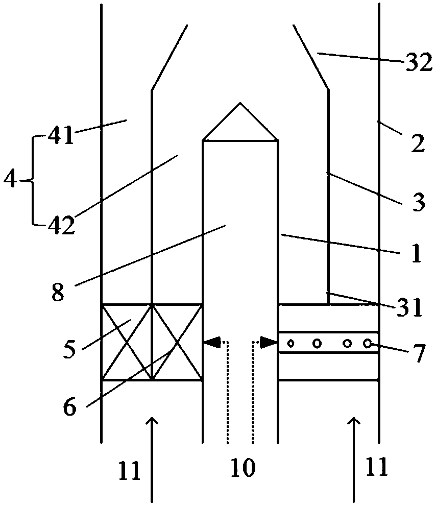
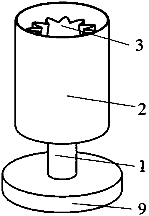
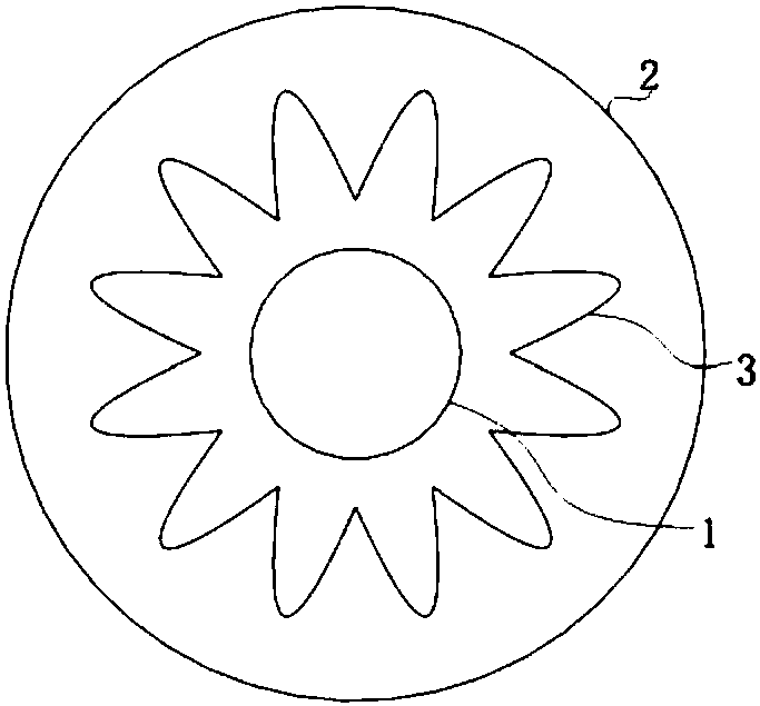
[0024] Such as Figure 1-3 As shown, the fuel nozzle according to the embodiment of the present invention includes a central body 1 , a shroud 2 , an inner cylinder 3 , an outer swirler 5 and an inner swirler 6 .

[0025] The shroud 2 fits on the central body 1 and is radially spaced apart from each other, so that an annular channel 4 is formed between the shroud 2 and the central body 1 .

[0026] The inner cylinder 3 has an inlet end 31 and an outlet end 32, such as figure 1 As shown, both the fuel 10 and the air 11 enter from the bottom up, the lower end of the inner cylinder 3 is the inlet end 31 , and the upper end is the outlet end 32 . The inner cylinde...


PUM


Abstract

The invention discloses a fuel nozzle and a combustor of a gas turbine. The fuel nozzle comprises a center body, a sleeve cover, an inner cylinder, an outer side swirler and an inner side swirler; thesleeve cover is arranged outside the center body in a sleeving mode, and an annular channel is formed between the sleeve cover and the center body; the inner cylinder is provided with an inlet end and an outlet end, the inner cylinder is arranged in the annular channel, so that the annular channel is divided into an outer annular channel between the inner cylinder and the sleeve cover and an inner annular channel between the inner cylinder and the center body, and the outlet end of the inner cylinder is of a lobe-shaped structure; and the outer side swirler is arranged in the outer annular channel, and the inner side swirler is arranged in the inner annular channel. According to the fuel nozzle and the combustor of the gas turbine, effect of fuel and air mixing is good, emission of pollutants can be reduced, the tempering risk can be effectively reduced, and the problem that a fuel nozzle is easily damaged due to the fact that the lobe-shaped structure is directly adopted to replace aswirler is avoided.

Description

technical field [0001] The invention relates to the technical field of gas turbines, in particular to a fuel nozzle and a combustor of the gas turbine. Background technique [0002] In the gas turbine, the air is compressed into high-pressure air by the compressor, enters the combustion chamber from the diffuser, enters the nozzle at the head of the combustion chamber after being turned, mixes with fuel in the nozzle, and then enters the flame tube for combustion. However, the uneven mixing of air and fuel in the nozzle will easily increase the emission of NOx and other pollutants, increase the local flame propagation speed, and bring risks such as flashback and flameout. [0003] In the related art, a lobe structure is used in the fuel nozzle to replace the existing swirler, which integrates the swirling flow and enhances the mixing effect of air and fuel. However, the above-mentioned fuel nozzle tends to have a low-velocity region in the lobe structure, and once flashback...

Claims


Application Information

Patent Timeline
Patent Type & Authority Applications(China)
IPC IPC(8): F23R3/28
Inventor 吕煊李珊珊杨旭刘小龙王昆薛彧
Owner CHINA UNITED GAS TURBINE TECH CO LTD
Why Eureka
Try Eureka