Method for manufacturing antenna and mobile device

A manufacturing method and mobile device technology, applied in the direction of antenna support/installation device, radiating element structure, etc., can solve the influence of mobile phone installation, the joint between the antenna and the plastic mobile phone back shell, the antenna and the plastic mobile phone back shell The problem of low precision

Inactive Publication Date: 2018-01-23
AAC PRECISE MFG TECH CHANGZHOU
View PDF6 Cites 2 Cited by
  • Summary
  • Abstract
  • Description
  • Claims
  • Application Information

AI Technical Summary

Problems solved by technology

Since both the FPC antenna and the plastic mobile phone back case are prone to elastic deformation, and the edges of the antenna and the mobile phone back case are bonded through non-planar surfaces, the bonding accuracy between the antenna and the plastic mobile phone back case is low, and the antenna is prone to bending. In addition, the antenna and the plastic mobile phone back shell are prone to loose fit, which makes the antenna occupy more installation space inside the mobile phone and affects the installation of other components in the mobile phone.

Method used


Image

  • Method for manufacturing antenna and mobile device
  • Method for manufacturing antenna and mobile device
  • Method for manufacturing antenna and mobile device

Examples


Embodiment Construction

[0052] The present invention will be described in further detail below through specific embodiments and in conjunction with the accompanying drawings.

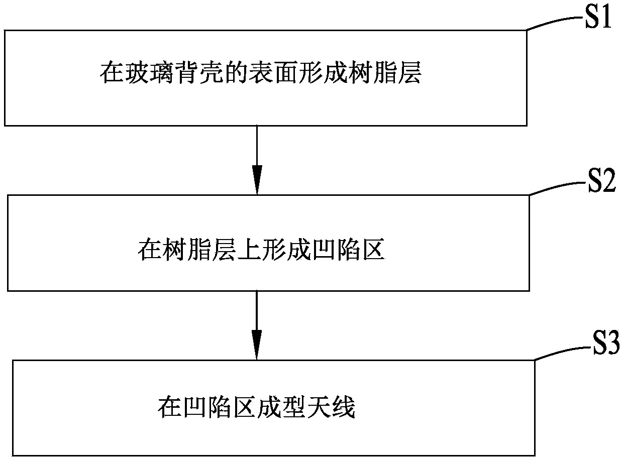
[0053] Such as figure 1 , Figure 5 , Figure 6 and Figure 7 As shown, among them, figure 1 A schematic flow chart of a method for manufacturing an antenna provided by an embodiment of the present invention, which includes the following steps:

[0054] S1, forming a resin layer 2 on the surface of the glass back shell 1;

[0055] The glass back shell 1 can specifically be a back shell made of glass material in a mobile device. The aforementioned back shell can be a flat back shell or a curved back shell; the staff can set the thickness of the glass back shell 1 according to actual needs. For example, the thickness of the glass back shell 1 may be between 0.3-2 mm. The resin layer 2 can be prepared in advance, and the resin layer 2 can be a film-like structure made of resin material, and the film-like resin layer 2 is ar...


PUM


Abstract

The invention relates to the field of the mobile communication technology, in particular, to a method for manufacturing an antenna and a mobile device. The provided manufacturing method comprises: S1,forming a resin layer on the surface of a glass back shell; S2, forming a recessed region on the resin layer; and S3, carrying out moulding of an antenna in the recessed region. According to the invention, the antenna manufactured by the method is not easy to bend and is in contact with a back shell of a mobile phone tightly, so that the mounting space occupied by the antenna inside mobile equipment is reduced.

Description

technical field [0001] The present invention relates to the technical field of mobile communication, in particular to an antenna manufacturing method, and also to a mobile device. Background technique [0002] With the development of science and technology, due to the superior performance of 3D glass, it can cooperate with the OLED screen to obtain higher image clarity, avoid the shielding of mobile phone signals in the 5G environment, and make mobile phone wireless charging technology possible. In the future, it is expected to become the standard configuration of mobile phone back shells. [0003] Traditional antenna design schemes, such as FPC antenna design and LDS antenna design applied to mobile phones, are to attach the antenna along the edge of the plastic mobile phone back case or directly make it on the plastic mobile phone back case. Since both the FPC antenna and the plastic mobile phone back shell are prone to elastic deformation, and the edge of the antenna and...

Claims


Application Information

Patent Timeline
Patent Type & Authority Applications(China)
IPC IPC(8): H01Q1/24H01Q1/38
Inventor 朱晓龙周礼义
Owner AAC PRECISE MFG TECH CHANGZHOU
Why Eureka
Try Eureka