
An electrical beam installation structure

An installation structure and electrical technology, applied in the direction of electrical components, substation/switch layout details, etc., can solve the problems of wasting manpower, increasing production costs, wasting installation time, etc., to improve installation efficiency, reduce bolt fixing steps, and simple structure Effect

Active Publication Date: 2019-09-10
BEIJING DONGFANG HUITONG ELECTRICAL COMPANY
View PDF2 Cites 0 Cited by
  • Summary
  • Abstract
  • Description
  • Claims
  • Application Information

AI Technical Summary

Problems solved by technology

[0003] When installing switchgear in the prior art, it is necessary to fix the electrical beam on the electrical vertical beam through bolts, screw multiple bolts to the electrical vertical beam, and then tighten them one by one, which wastes a lot of installation time and manpower, and greatly increases Cost of production

Method used


Image

  • An electrical beam installation structure
  • An electrical beam installation structure
  • An electrical beam installation structure

Examples


Embodiment Construction

[0029] The present invention will be described in further detail below in conjunction with the accompanying drawings.

[0030] In describing the invention, it is to be understood that the terms "centre", "upper", "lower", "front", "rear", "left", "right", "vertical", "horizontal" , "top", "bottom", "inner", "outer" and other indicated orientations or positional relationships are based on the orientations or positional relationships described in the drawings, and are only for the convenience of describing the invention and simplifying the description, rather than indicating Or imply that the device or element referred to must have a specific orientation, be constructed and operate in a specific orientation, and therefore should not be construed as limiting the invention.

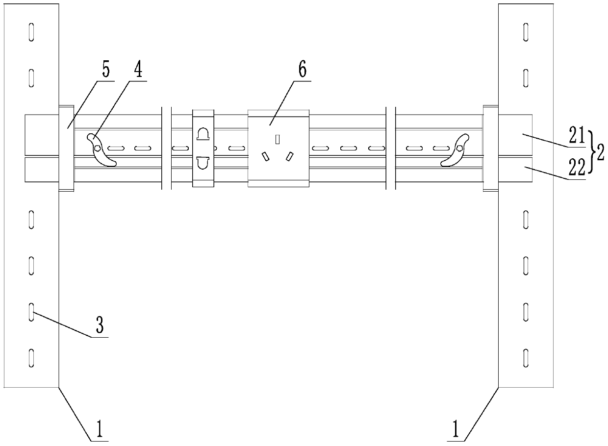
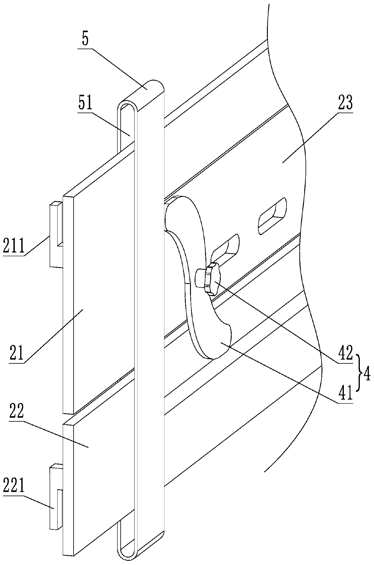
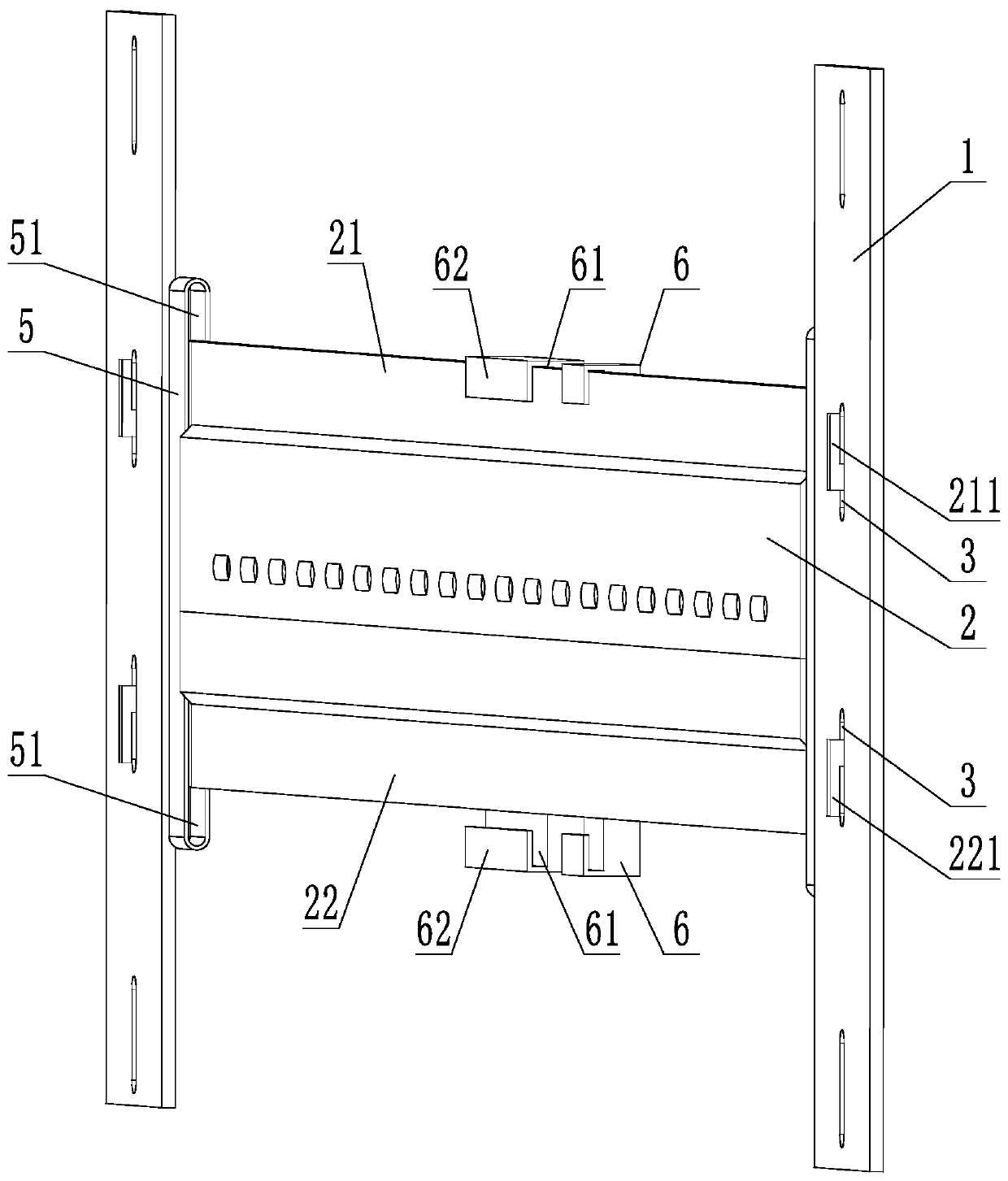
[0031] An electrical beam mounting structure, as attached figure 1 with 2 As shown, it consists of two electrical vertical beams 1 and one electrical horizontal beam 2, the two electrical vertical beams 1 a...


PUM


Abstract

The invention relates to an electrical beam installation structure. The electrical beam installation structure comprises two electrical vertical beams, an electrical cross beam and a plurality of modular holes, wherein the plurality of modular holes are arranged in the two electrical vertical beams at intervals and are used for installing the electrical cross beam, the electrical cross beam comprises an upper beam and a lower beam which are vertically and oppositely arranged and can get close to and deviate from each other, adjustment pieces, limitation pieces and clamping parts are arranged at two ends of the upper beam and the lower beam, the adjustment pieces are used for adjusting the distance between the upper beam and the lower beam, the limitation pieces are used for limiting movingdirections of the upper beam and the lower beam, the clamping parts are used for clamping the modular holes, and the electrical cross beam is clamped on the electrical vertical beams by the clampingparts. By the clamping mode, the electrical cross beam can be rapidly and conveniently fixed on the vertical beams, and meanwhile, switch equipment also can be fixed on the electrical cross beam.

Description

technical field [0001] The invention relates to the field of installation of power distribution equipment, in particular to an installation structure of an electric beam. Background technique [0002] Since the advent of complete switchgear, switchgear has been used in more and more places. With the advancement of science and technology, many large-scale electrical equipment are constantly being introduced. There are also higher requirements for the process of equipment and the convenience of installation. With the deepening of industrialization, the demand for power is also increasing, and the demand for switchgear is also increasing. In the actual design process, electrical designers have new requirements for the modularization of switchgear and the convenience of installation. [0003] When installing switchgear in the prior art, it is necessary to fix the electrical beam on the electrical vertical beam through bolts, screw multiple bolts to the electrical vertical beam...

Claims


Application Information

Patent Timeline
Patent Type & Authority Patents(China)
IPC IPC(8): H02B1/01
Inventor 马俊鹏
Owner BEIJING DONGFANG HUITONG ELECTRICAL COMPANY
Learn More