Automotive solid-state relay with PMOS tube and over-current protection

A solid-state relay and overcurrent protection circuit technology, applied in electrical components, electronic switches, pulse technology, etc., can solve the problems of complicated circuit redundancy, high cost, and hindering the popularization and use of solid-state relays.

Active Publication Date: 2018-01-23
SHANGHAI HUGONG AUTO ELECTRIC
View PDF11 Cites 3 Cited by
  • Summary
  • Abstract
  • Description
  • Claims
  • Application Information

AI Technical Summary

Problems solved by technology

[0004] In practice, if the existing solid-state relays are used for automotive control switches, the circuit redundancy is

Method used


Image

  • Automotive solid-state relay with PMOS tube and over-current protection
  • Automotive solid-state relay with PMOS tube and over-current protection

Examples


Embodiment Construction

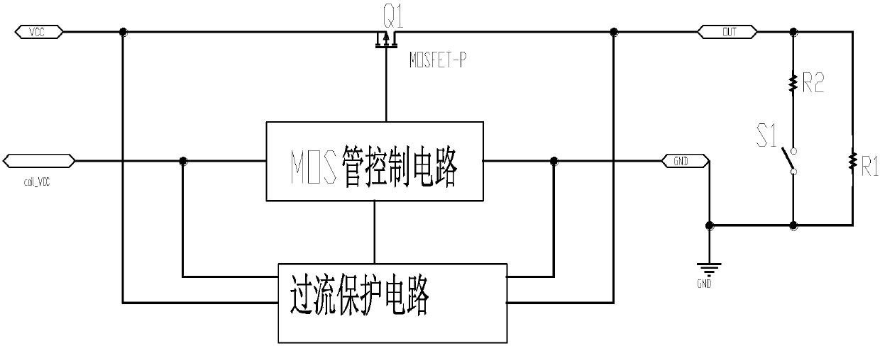
[0016] Such as figure 1 As shown, when coin_VCC (solid state relay control terminal power supply) is powered on, the MOS transistor control circuit drives the MOS transistor Q1 to conduct and output normally.

[0017] When the switch S1 is turned on, the output load increases instantly, and the MOS tube is in the overcurrent stage. The overcurrent protection circuit uses the RDS of the MOS tube itself (the on-resistance of the MOS tube, usually several milliohms to hundreds of milliohms) in the case of overcurrent voltage drop, when the current reaches a certain threshold, the trigger protection circuit turns off the MOS The tube control circuit turns off the MOS tube to realize the overcurrent protection of the MOS tube Q1. This switch S1 is used to simulate an overcurrent situation. When S1 is turned on, the load can be seen and a small resistance is connected, which means that a large load current is added.

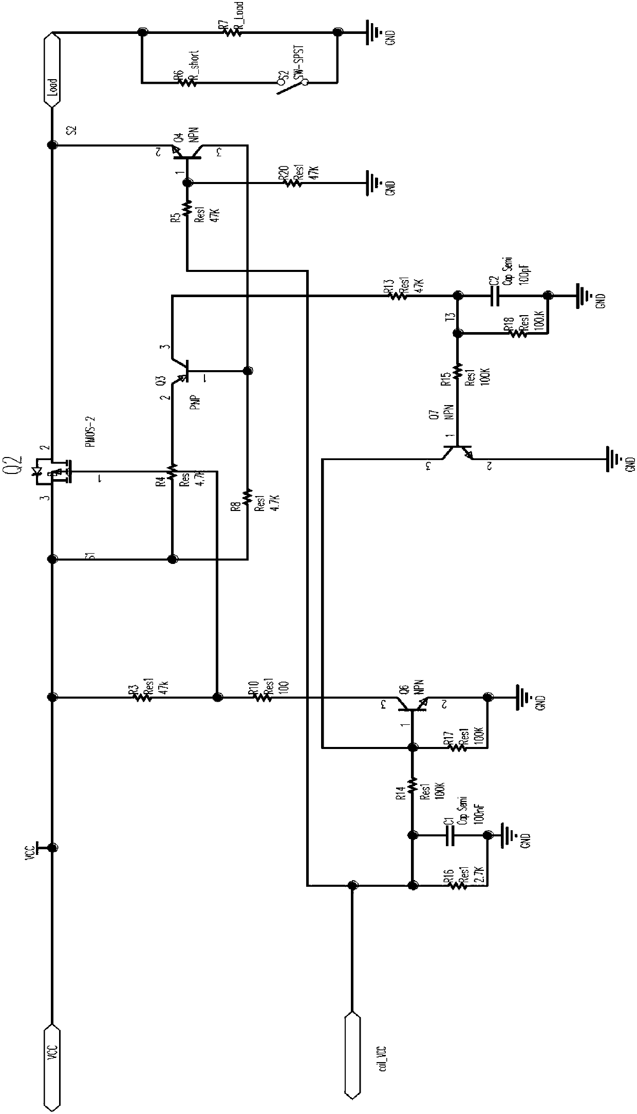
[0018] Such as figure 2 As shown, when the coil_VCC input is ...


PUM


Abstract

The invention provides an automotive solid-state relay with a PMOS tube and over-current protection. The source of the PMOS tube is connected with the positive electrode of a vehicle power supply. Thedrain is connected with a load. The gate is connected with a MOS tube control circuit. The MOS tube control circuit is powered by a solid-state relay control end power supply. The solid-state relay further comprises an over-current protection circuit connected with the MOS tube control circuit. The over-current protection circuit and the PMOS tube are connected in parallel on the drain and the source. After the solid-state relay control end power supply is powered on, the MOS tube control circuit drives the PMOS tube to turn on. When the PMOS tube is in the over-current condition, the over-current protection circuit uses the on-resistance of the PMOS tube to detect the voltage drop in the case of over-current. When the overload current is greater than a threshold, the protection functionis triggered, and the MOS tube control circuit is turned off. The PMOS tube is turned off to realize over-current protection of the PMOS tube.

Description

technical field [0001] The invention belongs to the technical field of automotive electronics, and in particular relates to an automotive solid-state relay including a PMOS tube with overcurrent protection. Background technique [0002] It is a common technology to use electromagnetic relays as switch control on existing cars. However, due to the limitation of the service life of mechanical materials and structures themselves, in the whole life cycle of vehicles, electromagnetic relays fail and have to be replaced. It is inevitable. At the same time, the sound made by the electromagnetic relay when it is pulled in is also unwelcome for some high-end cars. In this regard, solid state relays have unique advantages. [0003] The patent application with the application number CN200410041985.9 discloses a "DC solid-state power control method, which is characterized in that: the computer sends out a digital control signal for "turning on" or "turning off", and the digital contro...

Claims


Application Information

Patent Timeline
IPC IPC(8): H03K17/08
Inventor 李万霞郑轶民王瑞陈炳林
Owner SHANGHAI HUGONG AUTO ELECTRIC
Why Eureka
Try Eureka