
Overcurrent protection circuit and method, clock signal generation circuit and display device

An overcurrent protection circuit and a clock signal technology are applied in the fields of overcurrent protection circuits, clock signal generation circuits and display devices, and can solve the problems of a large number of level conversion circuits, disadvantageous area saving and the like

Pending Publication Date: 2021-01-22
BEIJING ESWIN COMPUTING TECH CO LTD +1
View PDF0 Cites 2 Cited by
  • Summary
  • Abstract
  • Description
  • Claims
  • Application Information

AI Technical Summary

Problems solved by technology

[0003] The main purpose of the present invention is to provide an overcurrent protection circuit, method, clock signal generation circuit and display device, which solves the problem of the number of level conversion circuits that need to be used when performing overcurrent protection on the clock signal generation circuit in the prior art. Many, which is not conducive to the problem of saving area

Method used


Image

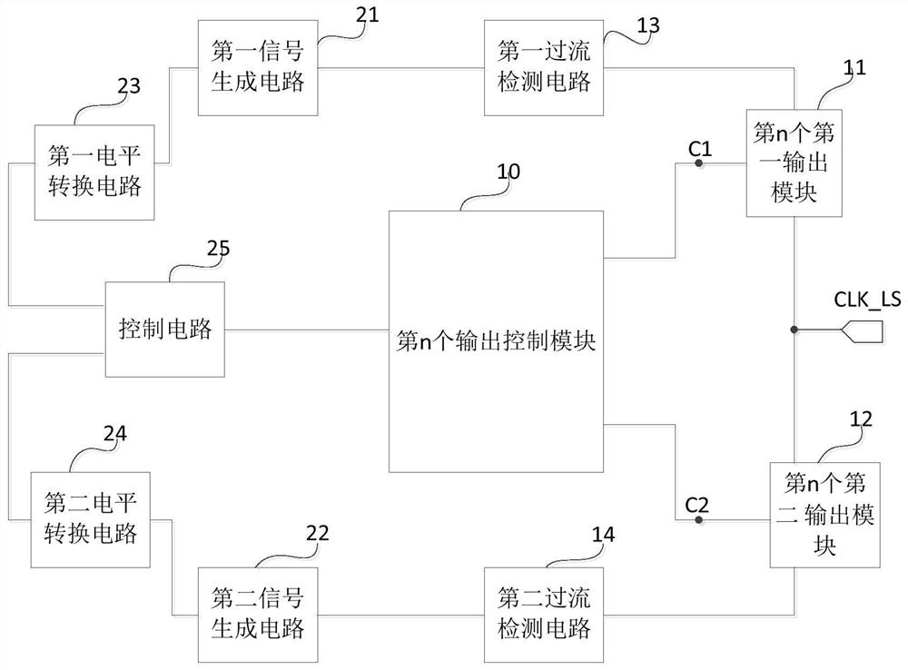
  • Overcurrent protection circuit and method, clock signal generation circuit and display device
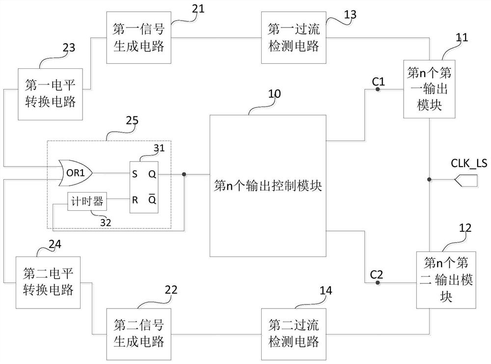
  • Overcurrent protection circuit and method, clock signal generation circuit and display device
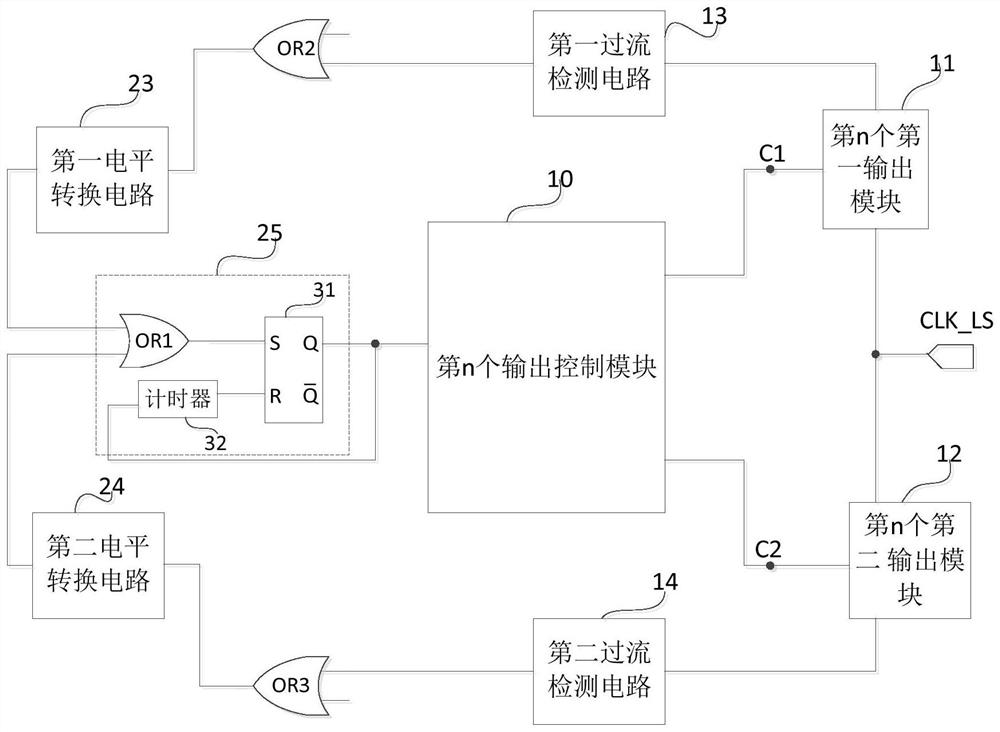
  • Overcurrent protection circuit and method, clock signal generation circuit and display device

Examples


Embodiment Construction

[0060] The following will clearly and completely describe the technical solutions in the embodiments of the present invention with reference to the accompanying drawings in the embodiments of the present invention. Obviously, the described embodiments are only some, not all, embodiments of the present invention. Based on the embodiments of the present invention, all other embodiments obtained by persons of ordinary skill in the art without making creative efforts belong to the protection scope of the present invention.

[0061] The transistors used in all embodiments of the present invention may be triodes, thin film transistors or field effect transistors or other devices with the same characteristics. In the embodiment of the present invention, in order to distinguish the two poles of the transistor except the control pole, one pole is called the first pole, and the other pole is called the second pole.

[0062] In actual operation, when the transistor is a triode, the contr...


PUM


Abstract

The invention provides an overcurrent protection circuit and a method, a clock signal generation circuit and a display device. The overcurrent protection circuit comprises N first over-current detection circuits, N second over-current detection circuits, a first signal generation circuit, a second signal generation circuit, a first level conversion circuit, a second level conversion circuit and acontrol circuit. The first signal generation circuit is used for outputting a first control signal to the first level conversion circuit when receiving a first overcurrent indication signal; the second signal generation circuit is used for outputting a second control signal to the second level conversion circuit when receiving a second overcurrent indication signal; the control circuit is used forproviding a turn-off control signal for the n output control module within a preset time after receiving the third control signal and / or the fourth control signal; wherein N is a positive integer, and n is a positive integer smaller than or equal to N. According to the invention, the overcurrent protection of the clock signal generation circuit can be realized only by adopting two level conversion circuits.

Description

technical field [0001] The invention relates to the technical field of overcurrent protection, in particular to an overcurrent protection circuit, a method, a clock signal generation circuit and a display device. Background technique [0002] In the gate drive circuit included in the display device, several clock signal generation circuits need to be used to convert the low-voltage clock signal into a high-voltage clock signal, which is used to supply power to the gate of the transistor; in order to prevent the output of the clock signal generation circuit from being short-circuited If the chip fails, overcurrent protection needs to be added, and the output power tube should be disconnected during protection. In the prior art, the overcurrent protection of the clock signal generation circuit requires a large number of level shifting circuits, which is not conducive to saving the area. Contents of the invention [0003] The main purpose of the present invention is to provi...

Claims


Application Information

Patent Timeline
Patent Type & Authority Applications(China)
IPC IPC(8): H02H3/08
CPCH02H3/08G05F1/573H02H3/093
Inventor 赵新江周拥华
Owner BEIJING ESWIN COMPUTING TECH CO LTD
Learn More