A medical equipment cleaning and disinfection device and disinfection method

A technology for cleaning and sterilizing medical equipment, applied in cleaning methods and utensils, lighting and heating equipment, chemical instruments and methods, etc., can solve the problems of broken glass jars, secondary pollution, time-consuming and labor-intensive, etc. time, the effect of avoiding recontamination

Inactive Publication Date: 2021-07-13
NORTH CHINA UNIVERSITY OF SCIENCE AND TECHNOLOGY
View PDF0 Cites 0 Cited by
  • Summary
  • Abstract
  • Description
  • Claims
  • Application Information

AI Technical Summary

Problems solved by technology

The glass jar is a commonly used cupping device in clinical practice, which can be used repeatedly. It needs to be cleaned and disinfected when it is reused. It can be applied to the clinic after reaching the medical level. The existing ultrasonic cleaning is easy to cause the glass jar to break and requires multiple steps. After cleaning, it is transferred to drying equipment for drying. During the transfer process, not only is it easy to cause secondary pollution, but it is also time-consuming and laborious. A medical equipment cleaning and disinfection device that can solve this problem needs further research and development.

Method used


Image

  • A medical equipment cleaning and disinfection device and disinfection method
  • A medical equipment cleaning and disinfection device and disinfection method
  • A medical equipment cleaning and disinfection device and disinfection method

Examples


Embodiment 1

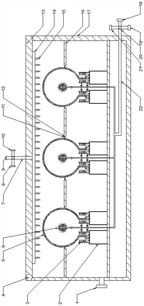
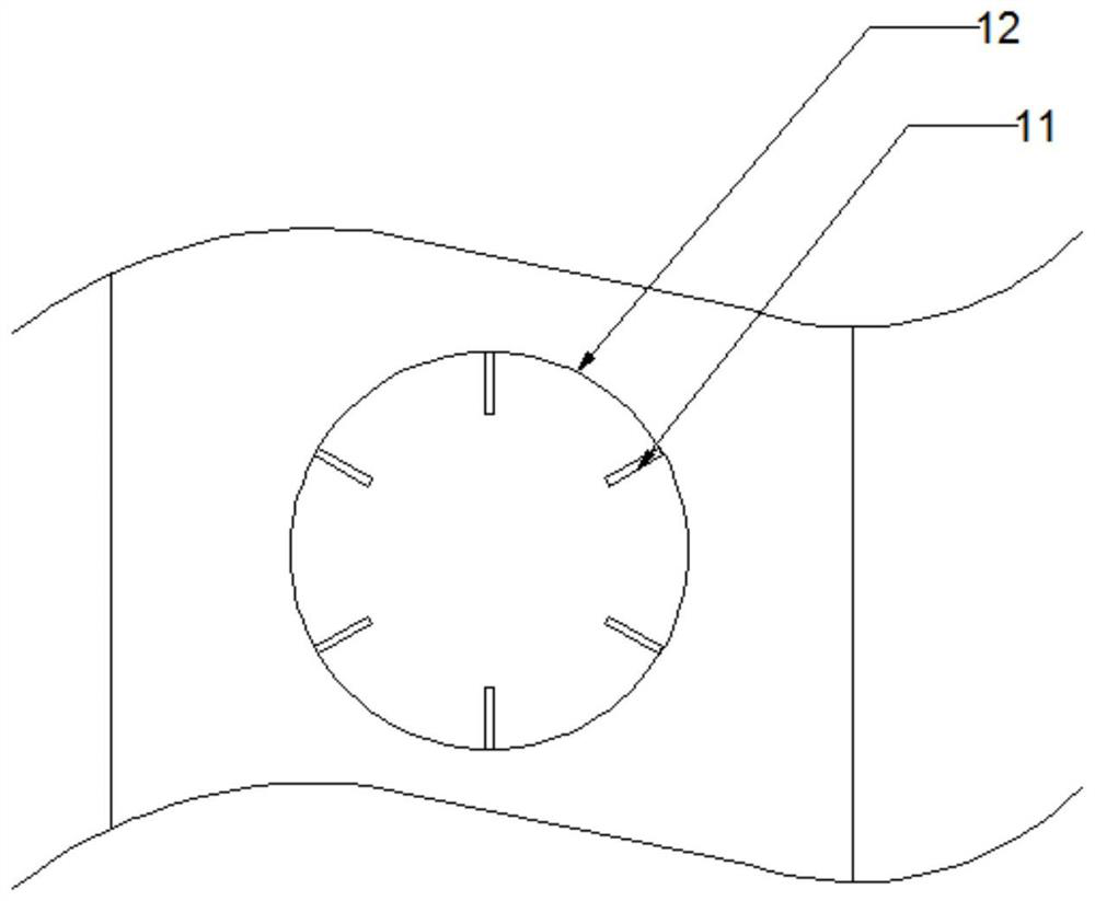
[0037] A cleaning and disinfection device for medical equipment of the present invention, comprising a sewage quick interface 1, a bracket 2, a secondary cleaning mechanism 3, a hinge 4, a glass jar 5, a primary cleaning head 6, a bracket 11, a fixing hole 12, and an upper cover 13. Liquid distribution air distribution plate 14, primary nozzle 15, partition 16, cleaning box 17;

[0038] One end of the upper cover 13 is hinged at the opening of the cleaning box 17 through a hinge 4, and the bottom end of the upper cover 13 facing the side of the cleaning box 17 is provided with a liquid distribution air distribution plate 14, and the liquid distribution air distribution plate The bottom end of 14 is provided with primary nozzles 15 distributed in a matrix, and the liquid and air distribution plate 14 is selectively connected to the cleaning agent supply source, the disinfectant supply source and the hot air supply source;

[0039] The bottom end of the cleaning box 17 is provid...

Embodiment 2

[0046] This embodiment is improved on the basis of Embodiment 1. The top of the liquid distribution and air distribution plate 14 is connected to the upper supply pipeline 7, and the end of the upper supply pipeline 7 is provided with a first four-way valve. A four-way valve is respectively connected to the first cleaning agent connection port 8 , the first disinfectant connection port 9 and the first hot air connection port 10 through pipelines.

[0047] As a preferred manner, the first cleaning agent connection port 8, the first disinfectant connection port 9, and the first hot air connection port 10 are all arranged on the outside of the upper cover 13, so as to facilitate the connection of corresponding supply pipes.

[0048]As a preferred manner, the first cleaning agent connection port 8 , the first disinfectant connection port 9 , and the first hot air connection port 10 all adopt quick connections.

[0049] The setting of the quick interface is convenient for quick ins...

Embodiment 3

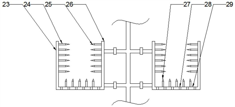
[0051] This embodiment is improved on the basis of Embodiment 1. The secondary cleaning mechanism 3 includes an outer annular liquid distribution air distribution plate 23 , an inner annular liquid distribution air distribution plate 26 and a lower liquid distribution air distribution plate 29 . The inner side of the annular liquid distribution wind plate 23 is evenly distributed with outer nozzles 24, the outer nozzles 24 point to the outer wall of the opening position of the glass jar 5, the inner nozzles 25 point to the inner wall of the opening position of the glass jar 5, and the lower nozzles 27 point to the inner wall of the opening position of the glass jar 5. At the opening position of the glass jar 5, there are a plurality of liquid-permeable holes 28 on the lower liquid-distributing air-distributing plate 29. The arrangement of the liquid-permeable holes 28 facilitates the downward flow of disinfectant and cleaning agent.

[0052] As a preferred manner, the secondary...


PUM


Abstract

The invention discloses a medical equipment cleaning and disinfection device and a cleaning and disinfection method. The bottom of the upper cover facing the cleaning box is provided with a liquid distributing wind plate, the bottom of the liquid distributing air plate is provided with a primary nozzle, and the liquid distributing cloth The air plate is selectively connected to the cleaning agent supply source, the disinfectant supply source and the hot air supply source; the bottom of the cleaning box is provided with a quick sewage discharge port, and the middle part is provided with a partition, and there are multiple partitions for fixing the glass tank on the partition. Fixed hole position, any fixed hole position is equipped with a circular distribution bracket, the center of the fixed hole position is equipped with a primary cleaning head, and the primary cleaning head is selectively connected to the cleaning agent supply source, the disinfectant supply source and the hot air supply Source; the secondary cleaning mechanism is set at the bottom of the partition and is set corresponding to the fixed hole position. The secondary cleaning mechanism corresponds to the opening position of the glass tank. The secondary cleaning mechanism selectively connects the cleaning agent supply source and the disinfectant supply source and hot air supply source. The invention has the advantages of high disinfection cleanliness and high operating efficiency.

Description

technical field [0001] The invention relates to the technical field of medical disinfection equipment, in particular to a medical equipment cleaning and disinfection device and a cleaning and disinfection method. Background technique [0002] Cupping is a kind of tool that uses cups and jars to remove the air in it by heat to generate negative pressure, so that it can be absorbed on the skin and cause blood stagnation. Ancient doctors used it to suck blood and drain pus when treating sores and abscesses, and later expanded its application to internal diseases such as tuberculosis and rheumatism. The glass jar is a commonly used cupping device in clinical practice, which can be used repeatedly. It needs to be cleaned and disinfected when it is reused. It can be applied to the clinic after reaching the medical level. The existing ultrasonic cleaning is easy to cause the glass jar to break and requires multiple steps. After cleaning, it is transferred to drying equipment for d...

Claims


Application Information

Patent Timeline
Patent Type & Authority Patents(China)
IPC IPC(8): B08B9/20B08B9/28A61L2/18F26B21/00
Inventor 刘颖田素红张万壮
Owner NORTH CHINA UNIVERSITY OF SCIENCE AND TECHNOLOGY
Why Eureka
Try Eureka