A detachable atomizing device
A technology of atomization device and atomization component, which is applied in the field of medical devices and can solve the problems of incomplete disinfection and the like
- Summary
- Abstract
- Description
- Claims
- Application Information
AI Technical Summary
Problems solved by technology
Method used
Image

Examples
Embodiment 1
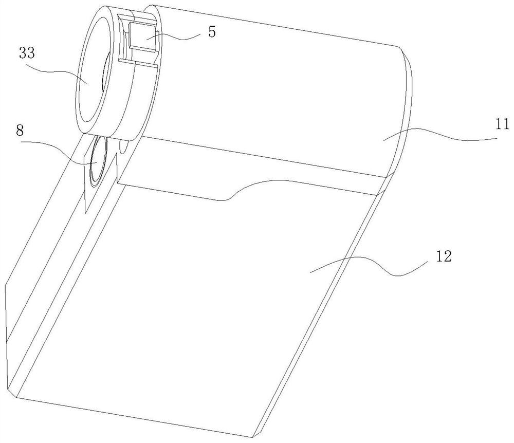
[0036] Please refer to Figure 1-3 , this embodiment provides a detachable atomization device, which includes:
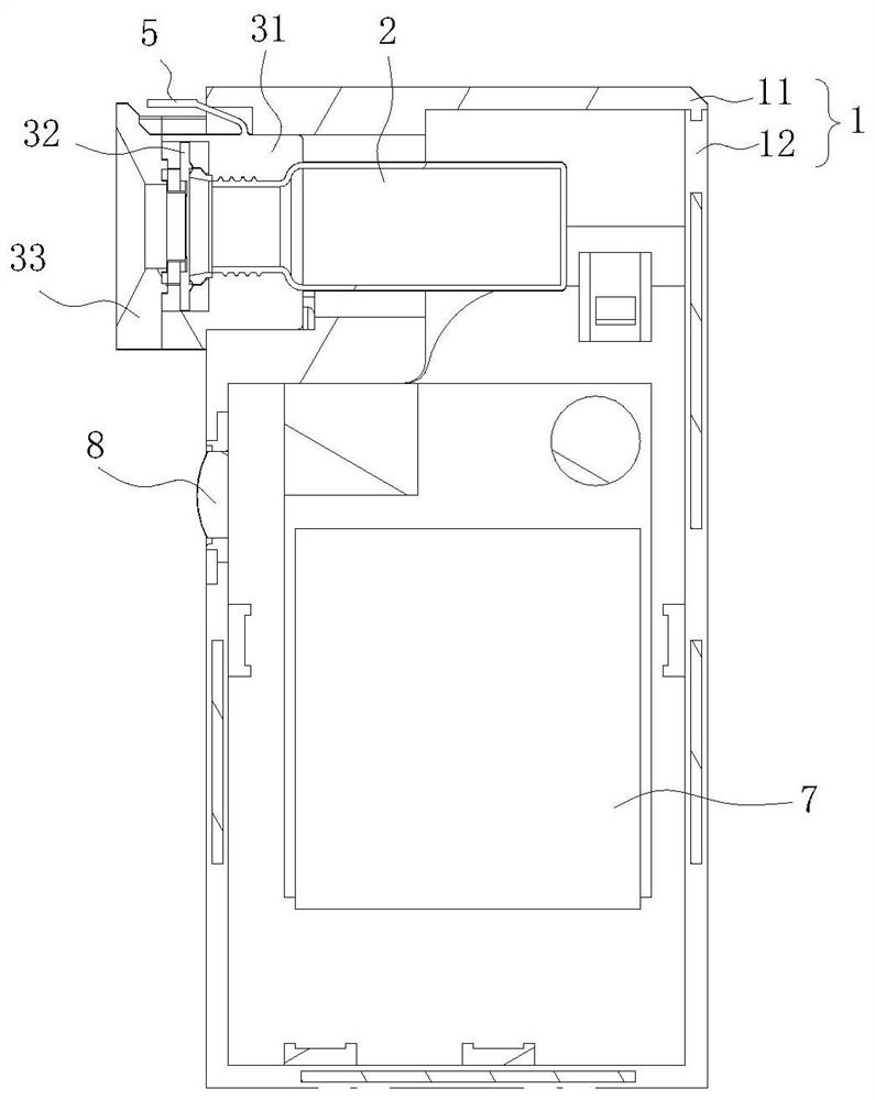
[0037] Housing 1, the housing 1 is a cavity structure;
[0038] An atomization assembly, the atomization assembly is detachably connected to the housing 1, the end of the atomization assembly connected to the housing 1 is connected to a liquid storage container 2, and the liquid storage container 2 is detachably connected to the atomization assembly.
[0039] Wherein, one end of the liquid storage container 2 close to the atomization assembly is provided with a limiting boss along its radial extension, and the end of the atomization assembly close to the liquid storage container 2 is provided with a fastener, and the fastener is clamped with the limiting boss. .
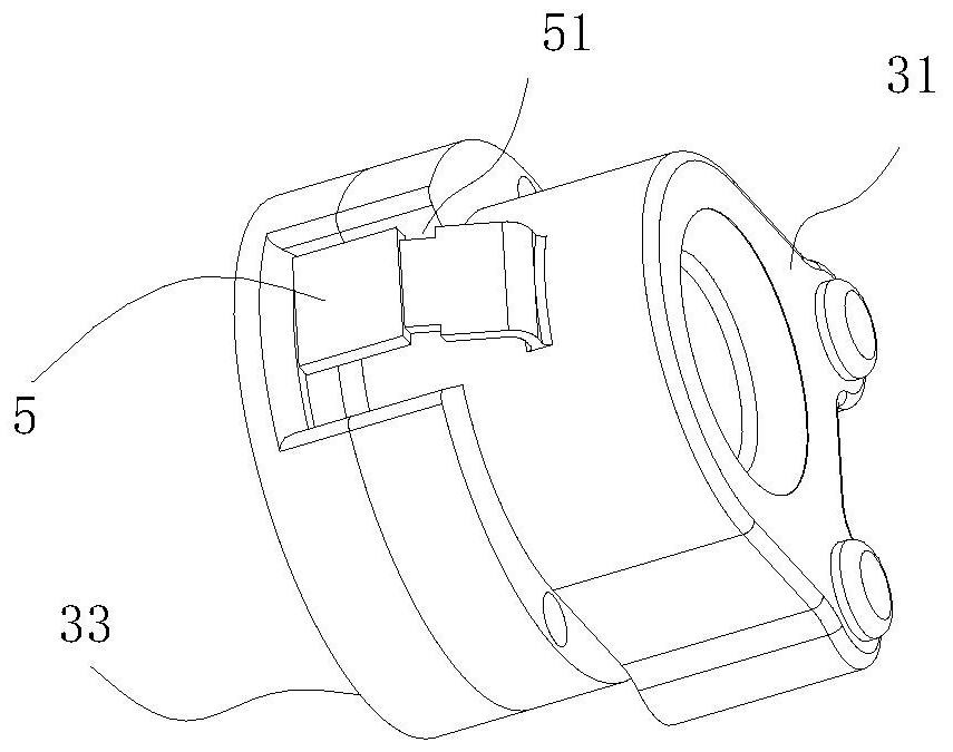
[0040] Such as figure 2 As shown, the above-mentioned atomization assembly includes a guide joint 31, an atomization sheet 32 for atomizing the liquid medicine, and an atomization outlet 33 for spray...
Embodiment 2
[0052] The difference between this embodiment and embodiment 1 is:
[0053] Such as Figure 5 , Figure 6 As shown, the fastener in this embodiment is that the end of the atomization component close to the liquid storage container 2 is provided with an elastic limit piece 4, and there is a gap between the elastic limit piece 4 and the atomization component. An installation groove is provided so that the liquid storage container 2 can be located on the elastic limit piece 4, the limit boss is a limit ring 21, and the end of the liquid storage container 2 close to the diversion joint 31 extends along its radial direction to limit the limit ring 21. To prevent the liquid storage container 2 from moving in the axial direction; when installed, the limit ring 21 is located in the gap between the elastic limit piece 4 and the atomization assembly so that the liquid storage container 2 can be fixed on one side of the atomization assembly .
[0054] In this embodiment, the specific ...
Embodiment 3
[0060] The difference between this embodiment and embodiment 1 is:
[0061] The fastener in this embodiment is that the end of the atomization component close to the liquid storage container is provided with an elastic limit piece, and there is a gap between the elastic limit piece and the atomization component, and the elastic limit piece is provided with a mounting groove to make the liquid storage container Can be located on the elastic limit piece, the limit boss is a limit ring, and the end of the liquid storage container close to the diversion joint extends along the radial direction to prevent the liquid storage container from moving in the axial direction; when installed, the limit The ring is located in the gap between the elastic limiting sheet and the atomization assembly so that the liquid storage container can be fixed on one side of the atomization assembly.
[0062] In this embodiment, the specific position of the elastic limiting piece is set at the end of the ...
PUM
 Abstract
Description
Claims
Application Information
 - R&D Engineer
- R&D Manager
- IP Professional
- Industry Leading Data Capabilities
- Powerful AI technology
- Patent DNA Extraction
Browse by: Latest US Patents, China's latest patents, Technical Efficacy Thesaurus, Application Domain, Technology Topic.
© 2024 PatSnap. All rights reserved.Legal|Privacy policy|Modern Slavery Act Transparency Statement|Sitemap