Automatic page turning mechanism
An automatic page-turning and page-turning technology, applied in the direction of conveyor objects, bookmarks, printing, etc., can solve the problems of high labor intensity and reduce production efficiency, and achieve the effect of reducing labor intensity and improving production efficiency
Active Publication Date: 2019-10-01
东莞市大升智能科技有限公司
View PDF7 Cites 3 Cited by
- Summary
- Abstract
- Description
- Claims
- Application Information
AI Technical Summary
Problems solved by technology
At present, manual page turning and manual processing are still used for batch marking, stamping, photographing or labeling of bound books and other page albums, which greatly reduces the production work. efficiency
Method used
View moreImage
Smart ImageViewing Examples
Examples
Embodiment Construction
Login to View More PUM
 Abstract
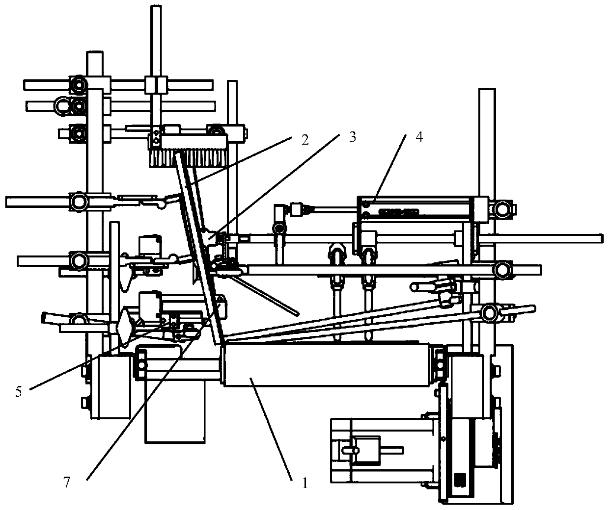
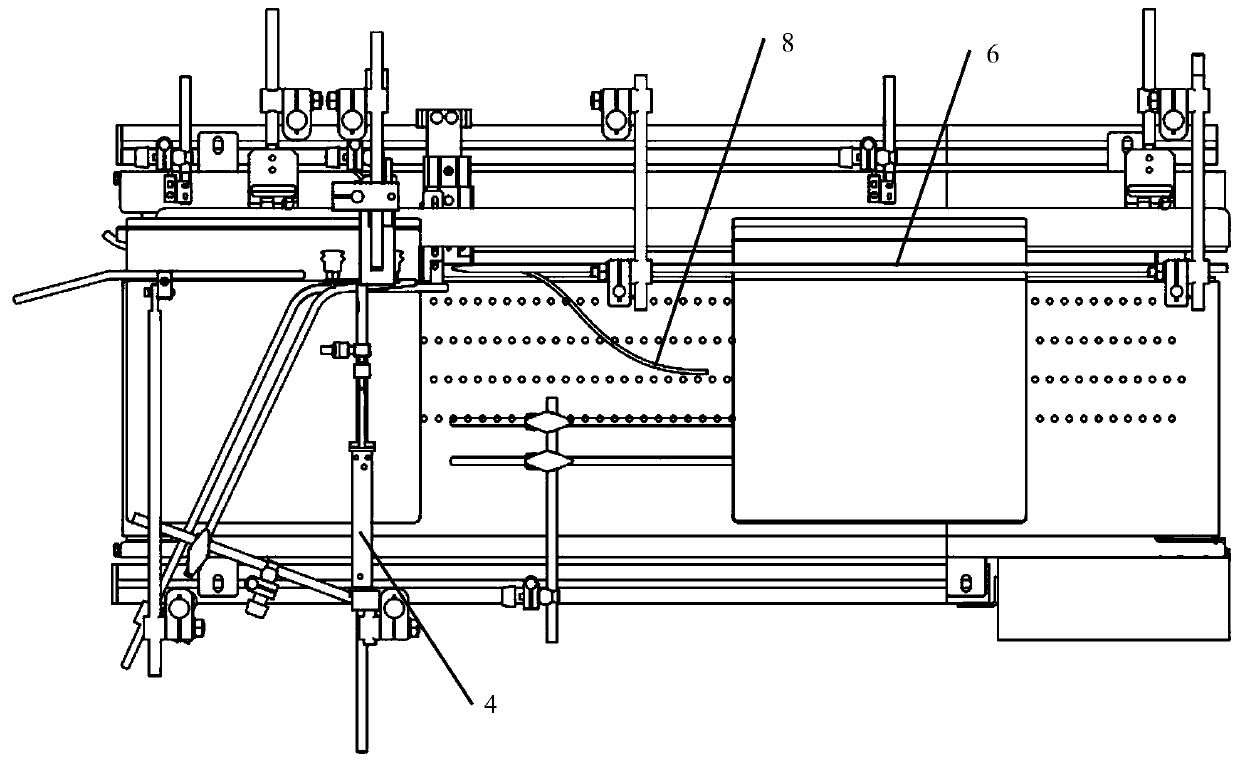
The invention discloses an automatic page turning mechanism. The automatic page turning mechanism comprises a conveyor, a vacuum suction nozzle, a page turning action air cylinder, a stop air cylinder, a page turning guiding rod and a supporting guiding plate. The conveyor comprises a conveying belt, the supporting guiding rod is arranged along the edge of one side of the conveying belt, and the supporting guiding plate is inclined outwards relative to the conveying belt. One end of the conveying belt is a feeding end, and the other end of the conveying belt is a discharging end. The vacuum suction nozzle and the page turning action air cylinder are arranged above the feeding end of the conveying belt. The air suction port end of the vacuum suction nozzle is close to and faces the supporting guiding plate, and the vacuum suction nozzle is connected with the page turning action air cylinder. The tail end of the page turning guiding rod is arranged on one side of the discharging end of the conveying belt, and the sharp end of the page turning guiding rod points at the feeding end of the conveying belt. The automatic page turning mechanism can conduct continuous and automatic page turning work on batched books, the production efficiency is greatly improved, and the labor intensity of workers is relieved.
Description
technical field The invention relates to the technical field of printing equipment, in particular to an automatic page turning mechanism. Background technique At present, manual page turning and manual processing are still used for batch marking, stamping, photographing or labeling of bound books and other page albums, which greatly reduces the production work. efficiency. For above-mentioned technical problem, be badly in need of developing a kind of machine that can turn pages automatically. Contents of the invention In view of this, the object of the present invention is to provide an automatic page-turning mechanism, which can realize continuous automatic page-turning work for batches of books. The present invention solves the above technical problems by the following technical means: An automatic page-turning mechanism of the present invention includes a conveyor, a vacuum nozzle, a page-turning action cylinder, a blocking cylinder, a page-turning guide rod, an...
Claims
Login to View More Application Information
Patent Timeline
 Patent Type & Authority Patents(China)
IPC IPC(8): B65G47/88B42D9/04
Inventor 王浩波
Owner 东莞市大升智能科技有限公司
- R&D Engineer
- R&D Manager
- IP Professional
- Industry Leading Data Capabilities
- Powerful AI technology
- Patent DNA Extraction
Learn More Browse by: Latest US Patents, China's latest patents, Technical Efficacy Thesaurus, Application Domain, Technology Topic, Popular Technical Reports.
© 2024 PatSnap. All rights reserved.Legal|Privacy policy|Modern Slavery Act Transparency Statement|Sitemap|About US| Contact US: help@patsnap.com


