Novel strong magnet-guided wire-passing device
A threading device and strong magnetic technology, applied in the field of wire harnesses, can solve the problems of destroying the integrity of corrugated pipes and inability to work with PVC pipes
- Summary
- Abstract
- Description
- Claims
- Application Information
AI Technical Summary
Problems solved by technology
Method used
Image

Examples
Embodiment Construction
[0019] In order to make the object, technical solution and advantages of the present invention more clear, the present invention will be further described in detail below in conjunction with the accompanying drawings and embodiments. It should be understood that the specific embodiments described here are only used to explain the present invention, not to limit the present invention.
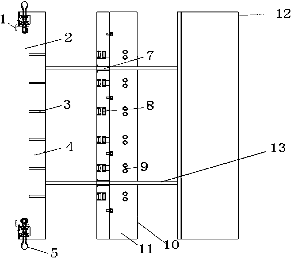
[0020] Such as figure 1 , 2 , 3, 4, 5, and 6, what the embodiment of the present invention provides is a novel strong magnetic guiding threading device, which includes a threading end, a locking tube end, a threading sliding end, and a rear end fixing seat, wherein the locking tube end 1. Two parallel telescopic slideways (13) are provided between the threading sliding end and the rear end fixed seat from the locking pipe end to the rear end fixed seat.
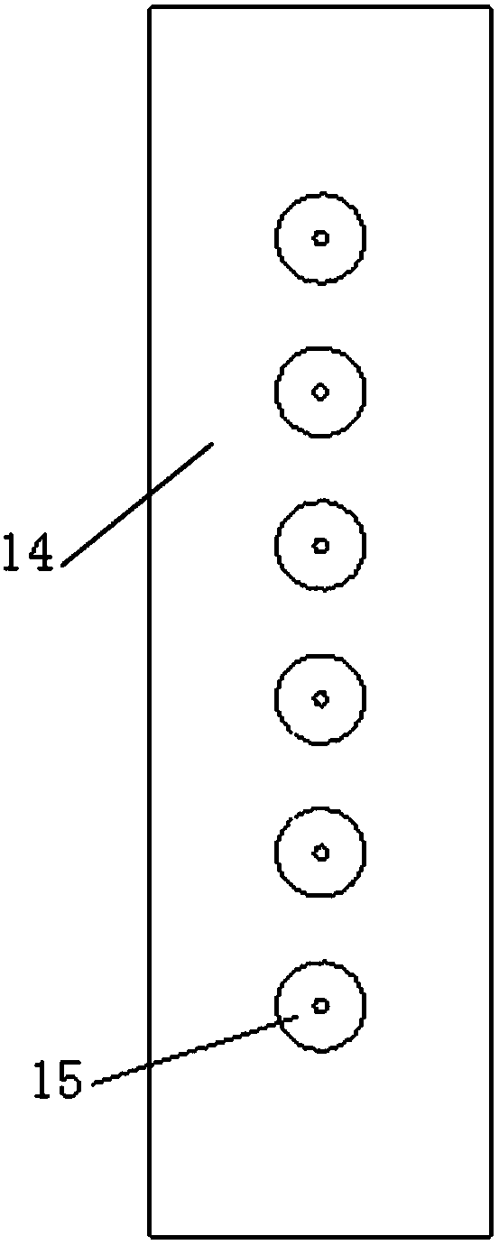
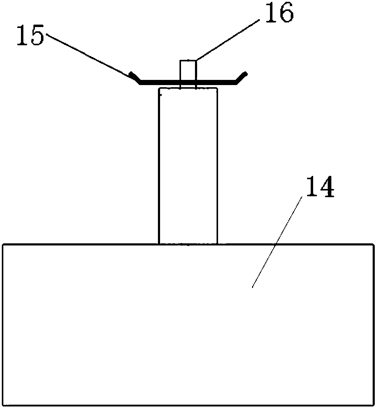
[0021] The pay-off end is made up of a tray base (14), a shaft (16), and a pay-off tray (15), wherein the tray base and the pay-off tray are...
PUM
 Abstract
Description
Claims
Application Information
PatSnap Eureka turns technology decisions into work you can execute. Powered by our Innovation Knowledge Graph, it runs expert workflows across engineering, life sciences, materials and intellectual property. Get your review-ready output in minutes.


