Vacuum packaging device

A technology of vacuum packaging and packaging table, which is applied in packaging, packaging machines, transportation and packaging, etc. It can solve the problems of unsatisfactory heat dissipation, affecting normal production, and poor shock absorption effect, achieving better cooling effect and simple structure , The effect of easy installation and disassembly

Inactive Publication Date: 2018-01-30
李敏芹
0 Cites 1 Cited by

AI-Extracted Technical Summary

Problems solved by technology

However, the shock absorption effect of the existing vacuum packaging equipment is not good, and the heat dissipation capac...

Method used

In addition, in one embodiment, for several groups of above-mentioned fixed pulleys 9, several groups of described fixed pulleys 9 are provided with at least two groups, and two groups of described fixed pulleys 9 are evenly distributed on the top of the base plate 5 . With this solution, at least two sets of fixed pulleys 9 are provided, and the two sets of fixed pulleys 9 are evenly distributed on the top of the bottom plate 5, making the adjustment of the height of the packaging platform 4 easier and quicker.
In sum, by means of above-mentioned technical scheme of the present invention, by being provided with universal wheel 2 at frame 1 bottom, and being provided with braking mechanism 3 on universal wheel 2, can realize the free movement of equipment and braking ability, making the use of the equipment more convenient and fast; by setting several sets of pulley blocks between the packing table 4 and the bottom plate 5, the adjustment of the packing table 4 can be realized, so that the packing table 4 can be freely adjusted, simple, convenient and fast; The casing 3 is provided with a waterproof diaphragm 4, which can strengthen the waterproof ability of the equipment and make the equipment have a longer service life; by setting the shock absorbing mechanism 13 to include a fixed block 14, a spring 15 is respectively arranged on both sides of the fixed block 14, and one end of the...

Abstract

The invention discloses a vacuum packaging device which comprises a framework. Universal wheels are arranged at the bottom of the framework, brake mechanisms are arranged on the universal wheels, a packaging table is arranged on the top of the framework, the framework is provided with a bottom plate which is arranged below the packaging table, a plurality of slide grooves are formed in the packaging table, damping mechanisms are fittingly arranged in the slide grooves and comprise fixing blocks, two springs are arranged on two sides of each fixing block, a ball is arranged at an end of each spring, damping springs are arranged on the tops of the fixing blocks, a packaging cover is arranged above the packaging table, the packaging table is movably connected with the packaging cover by a plurality of support rods which are arranged on the side surfaces of the packaging table, a heat dissipation layer is arranged in a shell of the packaging cover and comprises a first water tank and a second water tank, the first water tank is positioned on the upper side of the second water tank, a guide pipe is arranged between the first water tank and the second water tank, a water pump is arrangedon the guide pipe, and a condenser is arranged in the first water tank. The vacuum packaging device has the advantages that the vacuum packaging device is simple in structure, convenient to operate,good in damping performance and long in service life, and excellent cooling effects can be realized; the vacuum packaging device is convenient to move, ascend and descend.

Application Domain

Packaging under special atmospheric conditionsPackaging machines

Technology Topic

Water tanksVacuum packing +2

Image

  • Vacuum packaging device
  • Vacuum packaging device
  • Vacuum packaging device

Examples

  • Experimental program(1)

Example Embodiment

[0019] The technical solutions in the embodiments of the present invention will be clearly and completely described below in conjunction with the accompanying drawings in the embodiments of the present invention. Obviously, the described embodiments are only a part of the embodiments of the present invention, rather than all the embodiments. Based on the embodiments of the present invention, all other embodiments obtained by a person of ordinary skill in the art fall within the protection scope of the present invention.
[0020] According to an embodiment of the present invention, a vacuum packaging device is provided.
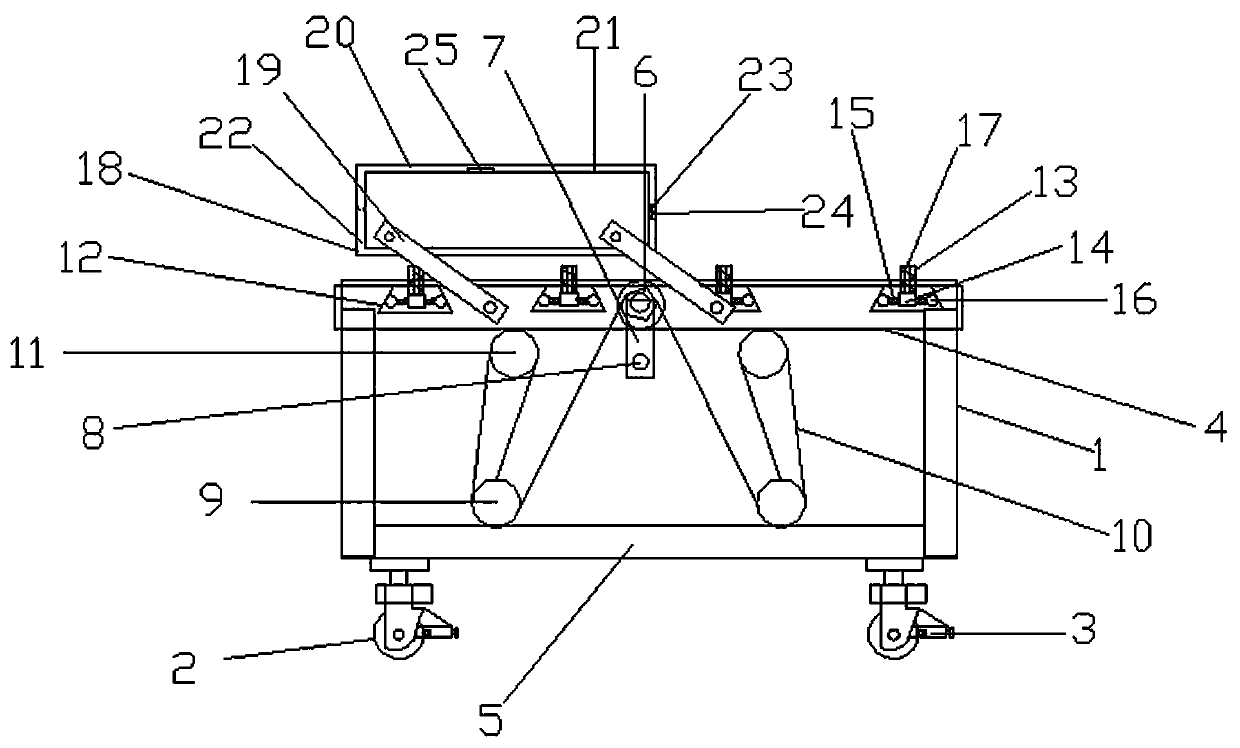
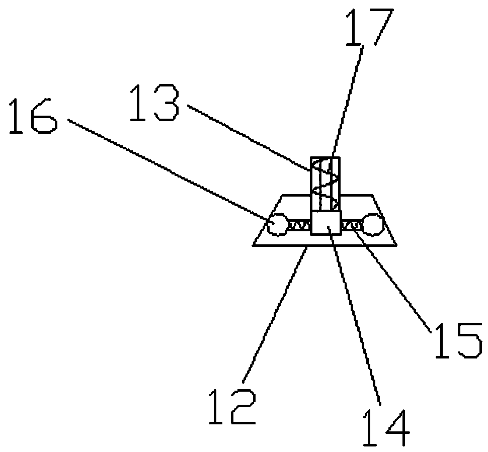
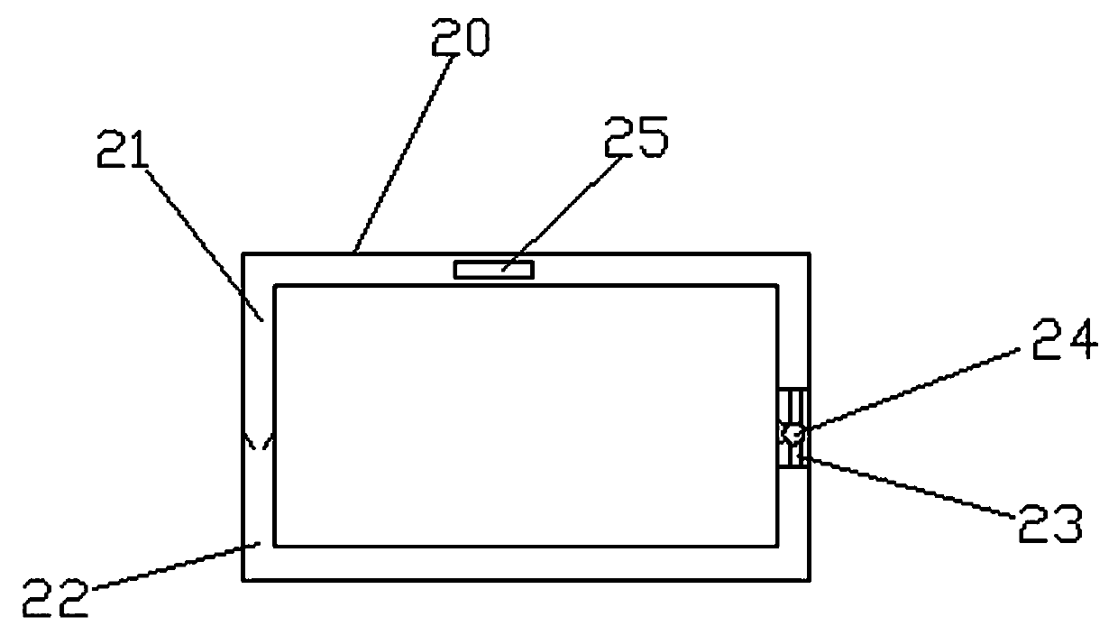
[0021] Such as Figure 1-3 As shown, the vacuum packaging device according to the embodiment of the present invention includes a frame 1, a universal wheel 2 is provided at the bottom of the frame 1, a braking mechanism 3 is provided on the universal wheel 2, and the frame 1 The top is provided with a packaging station 4, the rack 1 is provided with a bottom plate 5 below the packaging station 4, the packaging station 4 is provided with clamping teeth 6, and a connecting rod 7 is inserted into the clamping teeth 6, so One end of the connecting rod 7 penetrates the packaging table 4 with a rotating hand 8; the top of the bottom plate 5 is provided with a number of fixed pulleys 9, and there is a matching set between the packaging table 4 and the bottom plate 5. A chain 10 with a fixed pulley 9 vertically arranged, the teeth 6 meshing with the chain 10, the bottom of the packing table 4 is provided with a movable pulley 11 matching the fixed pulley 9, and the movable pulley 11 slides on the In the chain 10, the packing table 4 is provided with a plurality of sets of sliding grooves 12, and a shock-absorbing mechanism 13 is matched in the sliding grooves 12. The shock-absorbing mechanism 13 includes a fixed block 14 on both sides of the fixed block 14 Each is provided with a spring 15, one end of the spring 15 is connected to the fixed block 14, and the other end of the spring 15 is provided with a ball 16 that contacts the inner wall of the sliding groove 12, and the top of the fixed plate 14 A shock-absorbing spring 17 is provided, and a packaging cover 18 is arranged above the packaging table 4, and the packaging table 4 is movably connected with the packaging cover 18 by providing several groups of support rods 19 on the side. A heat dissipation layer 20 is provided. The heat dissipation layer 20 includes a water tank 21 and a water tank 22. The water tank 21 is located above the water tank 22, and a pipe 23 is provided between the water tank 21 and the water tank 22 A water pump 24 is provided on the conduit 23, and a condenser 25 is provided in the water tank 21.
[0022] In addition, in one embodiment, for the universal wheel 2 described above, the universal wheel 2 is provided with a rubber damping gasket. With this solution, the universal wheel 2 is provided with rubber damping gaskets, which can strengthen the damping capacity of the universal wheel 2 and make the universal wheel 2 have a longer service life.
[0023] In addition, in an embodiment, for the above-mentioned brake mechanism 3, the brake mechanism 3 is a hydraulic brake mechanism with elastic members. With this solution, the brake mechanism 3 is a hydraulic brake mechanism with elastic parts, which can enhance the braking effect of the universal wheel 2 and make the equipment more convenient and faster to use.
[0024] In addition, in one embodiment, for several groups of the above-mentioned fixed pulleys 9, at least two groups of the fixed pulleys 9 are provided, and the two groups of the fixed pulleys 9 are evenly distributed on the top of the bottom plate 5. With this solution, at least two sets of the fixed pulleys 9 are provided in several groups, and the two sets of the fixed pulleys 9 are evenly distributed on the top of the bottom plate 5, making the adjustment of the height of the packaging table 4 easier and faster.
[0025] In addition, in one embodiment, for a plurality of groups of the above-mentioned sliding grooves 12, at least four groups of the plurality of groups of the sliding grooves 12 are provided, and the four groups of the sliding grooves 12 are evenly distributed on the packaging table 4. With this solution, at least four groups of the chutes 12 are provided in several groups, and the four groups of the chutes 12 are evenly distributed on the packaging table 4.
[0026] In addition, in one embodiment, for the above-mentioned damping spring 17, the damping spring 17 is a rubber spring damping mechanism. With this solution, the damping spring 17 is a rubber spring damping mechanism, which can enhance the damping effect between the packaging table 4 and the packaging cover 18, is economical and durable, and makes the equipment more convenient to use.
[0027] In summary, with the above technical solution of the present invention, the universal wheel 2 is provided at the bottom of the frame 1, and the braking mechanism 3 is provided on the universal wheel 2, so that the equipment can move and brake freely. The ability to make the equipment more convenient and quick to use; by setting several sets of pulleys between the packaging table 4 and the bottom plate 5, the adjustment function of the packaging table 4 can be realized, so that the packaging table 4 can be adjusted freely, simply, conveniently and quickly; There is a waterproof diaphragm 4 on the outside, which can strengthen the waterproof capability of the equipment and make the equipment longer service life; by setting the shock absorption mechanism 13 including a fixed block 14, a spring 15 is provided on both sides of the fixed block 14, and one end of the spring 15 is connected to the fixed block 14 is connected, the other end of the spring 15 is provided with a ball 16, and the ball 16 is in contact with the inner wall of the chute 12. The top of the fixed plate 14 is provided with a shock-absorbing spring 17, which can absorb shock and make the installation and disassembly of the equipment easier; The heat dissipation layer 20 includes water tank one 21 and water tank two 22. Water tank one 21 is located above water tank two 22. A pipe 23 is provided between water tank one 21 and water tank two 22. A water pump 24 is provided on the pipe 23, and water tank one 21 is provided with condensation. The device 25 can circulate the water to cool the water and enhance the cooling capacity of the heat dissipation layer 20, so that the cooling effect of the equipment is better and the service life of the equipment is longer; the vacuum packaging device has simple structure, convenient operation, good cooling effect, and shock absorption performance Good, long service life, and easy to move up and down.
[0028] The above descriptions are only preferred embodiments of the present invention and are not intended to limit the present invention. Any modification, equivalent replacement, improvement, etc. made within the spirit and principle of the present invention shall be included in the present invention. Within the scope of protection.

PUM

no PUM

Description & Claims & Application Information

We can also present the details of the Description, Claims and Application information to help users get a comprehensive understanding of the technical details of the patent, such as background art, summary of invention, brief description of drawings, description of embodiments, and other original content. On the other hand, users can also determine the specific scope of protection of the technology through the list of claims; as well as understand the changes in the life cycle of the technology with the presentation of the patent timeline. Login to view more.

Similar technology patents

Synthesis method of polyamide polyamine resin

Owner:佛山市帕里达新材料科技有限公司

Classification and recommendation of technical efficacy words

  • Improve water resistance

Polyacrylate emulsion with high water resistance and preparation method thereof

InactiveCN101525399AImprove water resistanceOvercome Migration
Owner:SHANGHAI APPLIED TECHNOLOGIES COLLEGE

Aqueous composite adhesive and preparation method and use thereof

InactiveCN101768416AImprove water resistanceHigh composite strength
Owner:BEIJING COMENS NEW MATERIALS

Preparation method of graft copolymer for surface sizing

ActiveCN102127191AImprove water resistanceImprove retention
Owner:JIANGSU FEYMER TECH

Inorganic heat-insulating mortar and preparation method thereof

Owner:HUNAN NONFERROUS ENVIRONMENTAL PROTECTION BUILDING MATERIALS
Why Eureka
Try Eureka