
Lift type drain device, toilet bowl with same and drain control method

An excretion device and a lift-type technology are applied in the fields of elevating excretion devices, toilets and excretion control, which can solve the problems of easy scaling in the bucket, sewage backflow, cumbersome dredging work, etc. Effect

Pending Publication Date: 2018-01-30
宁波酷客卫浴科技有限公司
View PDF5 Cites 0 Cited by
  • Summary
  • Abstract
  • Description
  • Claims
  • Application Information

AI Technical Summary

Problems solved by technology

In addition to wasting water resources, the traditional toilet drainage device also has problems in use safety and maintenance; because it needs to store a certain amount of water in the elbow to seal, and its rear end is directly connected to the sewage pipe Yes, during use, we often see reports of toilet odor backfilling, sewage backfilling, and even bacteria, viruses, fly maggots, rat snakes and other animals crawling out, which brings great safety hazards to users; while in use In terms of maintenance, the S-shaped pipe is also very easy to block, and some waste paper or solid waste is very easy to cause blockage after entering, and once a large amount of blockage occurs, the dredging work is also cumbersome and tiring
[0003] On the other hand, the traditional submerged water elbow will produce sewage backflow when the drainage is about to end, which is unavoidable by the siphon effect; There is dirt, so on the one hand, it will easily cause scaling in the barrel, on the other hand, it will also cause unnecessary waste of water resources

Method used


Image

  • Lift type drain device, toilet bowl with same and drain control method
  • Lift type drain device, toilet bowl with same and drain control method
  • Lift type drain device, toilet bowl with same and drain control method

Examples


Embodiment Construction

[0044] The present invention will be described in detail below in conjunction with the accompanying drawings, so that those skilled in the art can better understand the present invention, so as to define the protection scope of the present invention more clearly.

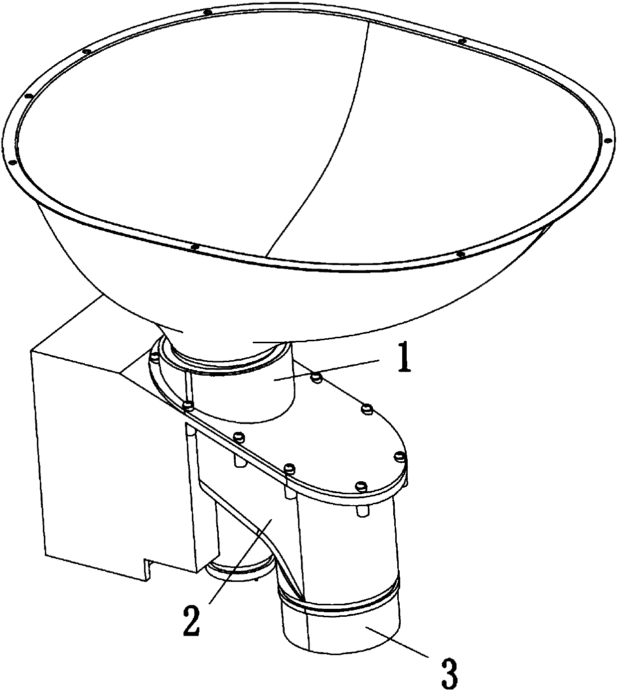
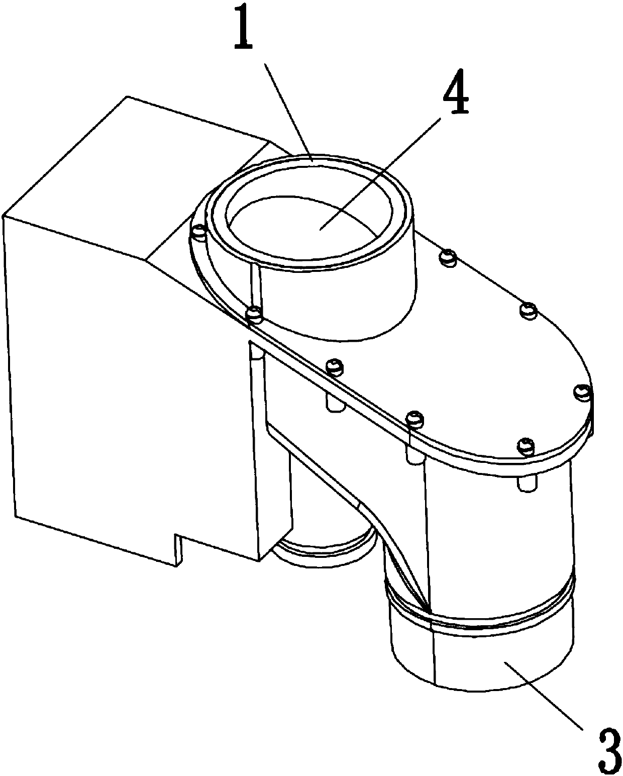
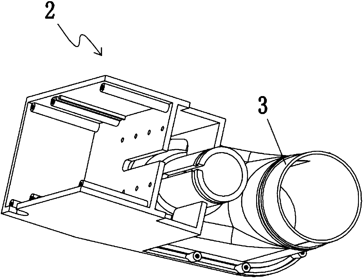
[0045] A lifting type discharge device is composed of a discharge port 1, a housing 2, a sewage connection port 3, a lifting type discharge valve 4, a transmission device 5, a driving device 6, an operation button (not shown in the figure) and a control device ( not shown) composition; the housing 2 is provided with a discharge pipeline for excrement discharge, the housing 2 is also provided with an inlet and an outlet, the inlet and the outlet are respectively arranged at the two ends of the discharge pipeline, and the inlet , the discharge pipeline and the outlet are configured to form a complete discharge pipeline for the excrement to flow through; the discharge port and the sewage connection port are respectively...


PUM


Abstract

The invention discloses a lift type drain device which comprises a drain opening, a shell, a drain connector, a lift type drain valve, a transmission gear, a driving device, operating buttons and a control device. The lift type drain valve is arranged in a discharge pipeline and is configured in such a manner that the discharge pipeline can be opened or closed by the aid of the lift type drain valve; the lift type drain valve comprises a sealing portion and a connecting portion, the transmission gear comprises a connecting piece, a guide piece and a lift block, and the lift block is fittinglyarranged in a guide groove; the driving device comprises a motor, a spiral lead screw and sensors, threads are spirally arranged on the outer wall of the spiral lead screw, a through hole is formed inthe lift block, the spiral lead screw can penetrate the through hole, threads which can be matched with the spiral lead screw are arranged in the through hole, or a plug pin which can be matched withthe threads of the spiral lead screw is arranged in the through hole. The lift type drain device has the advantages that various shortcomings of the traditional sinking bent pipe structures can be overcome by the aid of the lift type drain device; good water saving effects can be realized by the lift type drain device, the lift type drain device is good in safety and difficult to block and can beused in wide scenes, sewage backflow can be prevented, and the like.

Description

technical field [0001] The invention belongs to the technical field of bathroom equipment, and in particular relates to a lift-type drainage device with obvious water-saving effect, not easy to be blocked, good in safety and capable of preventing siphon backflow, a toilet with the device and a drainage control method. Background technique [0002] Water conservation in toilets has always been a global concern. At present, the common toilets on the market generally adopt a drainage device with a submerged elbow structure. There is a complete pipeline inside, which is in the shape of an S-shaped sideways. The water storage area at the bottom of the pool is large, and it usually takes 3 -6 liters of water to flush well, older toilets require more to flush. In addition to wasting water resources, the traditional toilet drainage device also has problems in use safety and maintenance; because it needs to store a certain amount of water in the elbow to seal, and its rear end is di...

Claims


Application Information

Patent Timeline
Patent Type & Authority Applications(China)
IPC IPC(8): E03D11/02E03D11/13
CPCY02A50/30
Inventor 徐建峰
Owner 宁波酷客卫浴科技有限公司
Learn More