Idle wheel mounting component

A technology for installing components and idlers, which is applied to machines/engines, mechanical equipment, etc., can solve the problems of easy breakage of the idler bracket, reduce the reliability of engine operation, and cannot change the transmission ratio, so as to prevent breakage and improve reliability. , the effect of reducing the vibration force value

Pending Publication Date: 2018-01-30
CHONGQING SOKON IND GRP CO LTD
View PDF6 Cites 1 Cited by
  • Summary
  • Abstract
  • Description
  • Claims
  • Application Information

AI Technical Summary

Problems solved by technology

[0002] The idler gear refers to the gear that acts as a transmission between two transmission gears that are not in contact with each other, and meshes with these two gears at the same time to change the direction of rotation of the driven gear so that it is the same as the driving gear; its function is only to change the direction of rotation The transmission ratio cannot be changed; the engine idler is one of the front-end gear trains; the engine idler is installed on the engine block through the idler bracket. Due to the constraints of the installation space, the idler bracket is a cantilever beam structure (that is, one end There is an engine mounting point, and the other end is suspended because there is no engine mounting point), which makes the idler bracket prone to breakage in vibration conditions, reducing the reliability of the engine operation

Method used


Image

  • Idle wheel mounting component
  • Idle wheel mounting component

Examples


Embodiment Construction

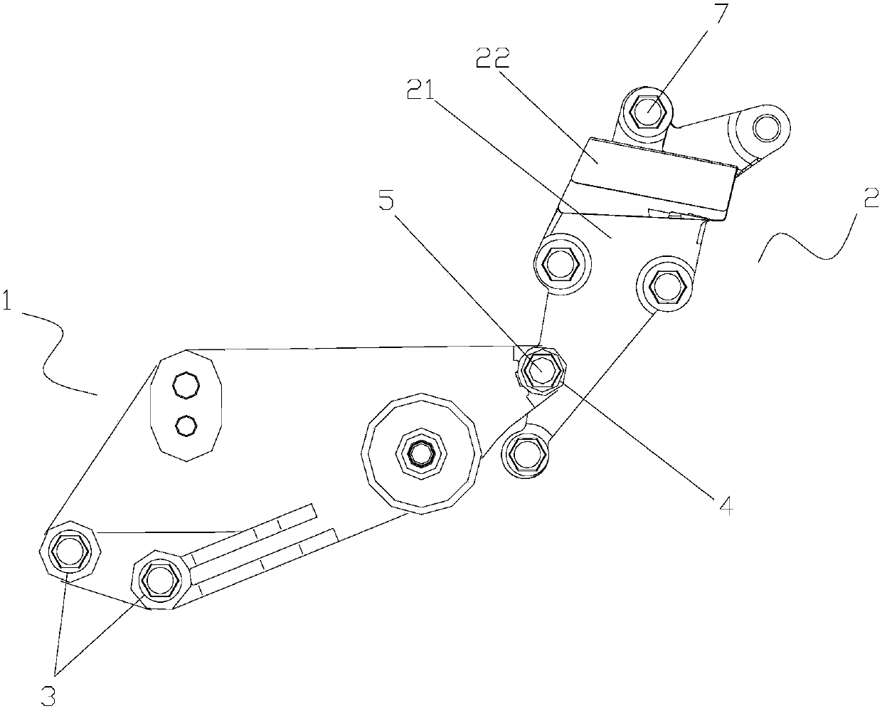
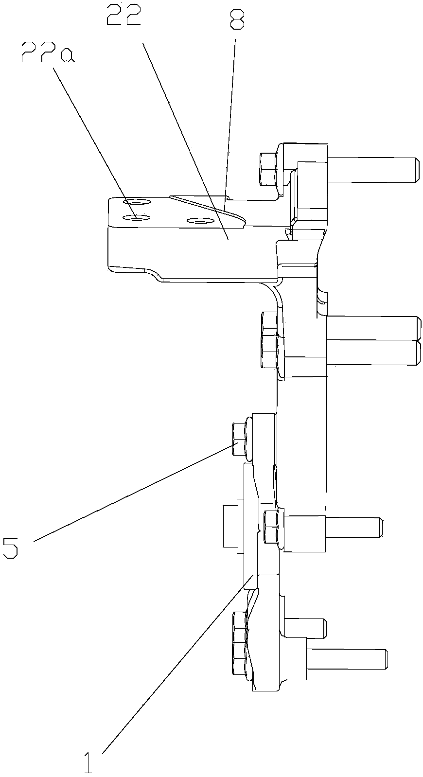
[0020] figure 1 It is the front view of the present invention, figure 2 It is the right side view of the present invention, as shown in the figure: the idler installation assembly of this embodiment includes an idler bracket 1 for installing an idler and a suspension bracket 2 for installing an engine suspension, and the idler The left end of the bracket 1 is provided with an engine fixing position I3 for fixing to the engine block, and the right end of the idler bracket 1 is provided with a bracket fixing position 4 for fixing to the suspension bracket 2; figure 1 The direction shown shall prevail; the engine fixing position I3 is an engine fixing hole structure; one end of the idler bracket 1 can be fixed to the engine block, and the other end is fixed to the suspension bracket 2 through the bracket fixing position 4. There are support points at both ends, thus changing the cantilever beam structure of the idler bracket 1 in the past, so that the idler bracket 1 can be sup...


PUM

PropertyMeasurementUnit
thicknessaaaaaaaaaa
current efficiencyaaaaaaaaaa

Abstract

The invention discloses an idle wheel mounting component. The idle wheel mounting component comprises an idle wheel support used for mounting an idle wheel and a suspension carrier used for mounting of an engine suspension. The left end of the idle wheel support is provided with an engine fixing position I fixed to an engine cylinder body, and the right end of the idle wheel support is provided with a carrier fixing position fixed to the suspension carrier. The idle wheel mounting component has advantages that one end of the idle wheel support can be fixed to the engine cylinder body while theother end of the idle wheel support is fixed to the suspension carrier through the carrier fixing position, two ends of the idle wheel support both have supporting points, and accordingly a cantilever structure of an existing idle wheel support is changed, the idle wheel support is supported stably, a shaking force value is decreased, breakage of the idle wheel support is effectively prevented, and operating reliability of an engine is improved.

Description

technical field [0001] The invention relates to an engine component, in particular to an idler gear installation assembly. Background technique [0002] The idler gear refers to the gear that acts as a transmission between two transmission gears that are not in contact with each other, and meshes with these two gears at the same time to change the direction of rotation of the driven gear so that it is the same as the driving gear; its function is only to change the direction of rotation The transmission ratio cannot be changed; the engine idler is one of the front-end gear trains; the engine idler is installed on the engine block through the idler bracket. Due to the constraints of the installation space, the idler bracket is a cantilever beam structure (that is, one end There is an engine mounting point, and the other end is suspended because there is no engine mounting point), which makes the idler bracket prone to breakage in vibration conditions, reducing the reliability...

Claims


Application Information

Patent Timeline
Patent Type & Authority Applications(China)
IPC IPC(8): F02B67/04C25D3/38
Inventor 凌青海刘维李祥江黄祥柱
Owner CHONGQING SOKON IND GRP CO LTD
Why Eureka
Try Eureka