Low-head and high flow water turbine machine

一种大流量、低水头的技术,应用在机械设备、水力发电、发动机元件等方向,能够解决无法产生较稳定转速、占用水轮轮缘面积、水轮流入及流出范围减少等问题

Inactive Publication Date: 2018-01-30
赖融毅
View PDF8 Cites 2 Cited by
  • Summary
  • Abstract
  • Description
  • Claims
  • Application Information

AI Technical Summary

Problems solved by technology

However, the above-mentioned patent still has some defects in actual operation. Although it has a movable gate to increase or decrease the cross-sectional area of ​​the water, the moving direction of the movable gate is to move along the periphery of the vertical axis water turbine in an arc. , which makes the gate occupy a lot of the rim area of ​​the water wheel, which reduces the inflow and outflow range of the water wheel and affects the inflow of the water turbine; in addition, the angle of the water inflow direction of the water wheel is not as recommended by various through-flow water turbine research institutes. Good angle, so the efficiency of its commercial products is about 0.3 ~ 0.4 is not high
In addition, when the cross-sectional area of ​​the water is adjusted, the machine cannot produce a relatively stable speed for different flows, because it can be seen from the patent drawing that its purpose is only to adjust The amount of water impacting the turbine does not control the angle at which the water enters the turbine. Therefore, when the movable gate is fully closed, water from the upstream side cannot enter the interior of the turbine. When the movable gate is opened, water can flow from the two phases. Adjacent water turbines flow through each other. Therefore, at different flow rates, different openings of the gates cause the water to enter the vertical axis water wheel at different average water inlet angles, and the uneven changes in the speed and output of the water wheel must be regulated by other equipment. From the above, we can know that there is still room for improvement

Method used


Image

  • Low-head and high flow water turbine machine
  • Low-head and high flow water turbine machine
  • Low-head and high flow water turbine machine

Examples


Embodiment Construction

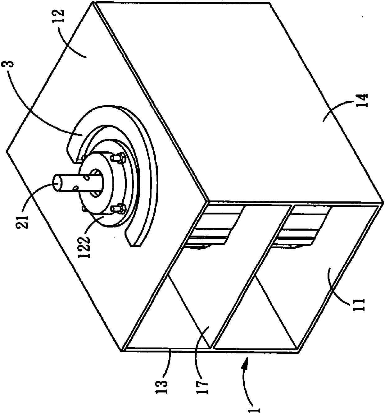
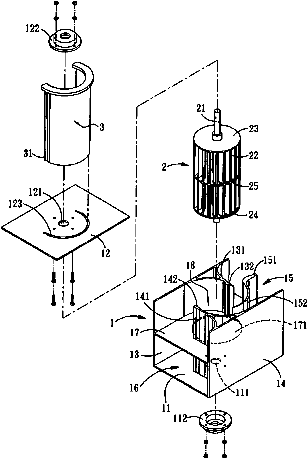
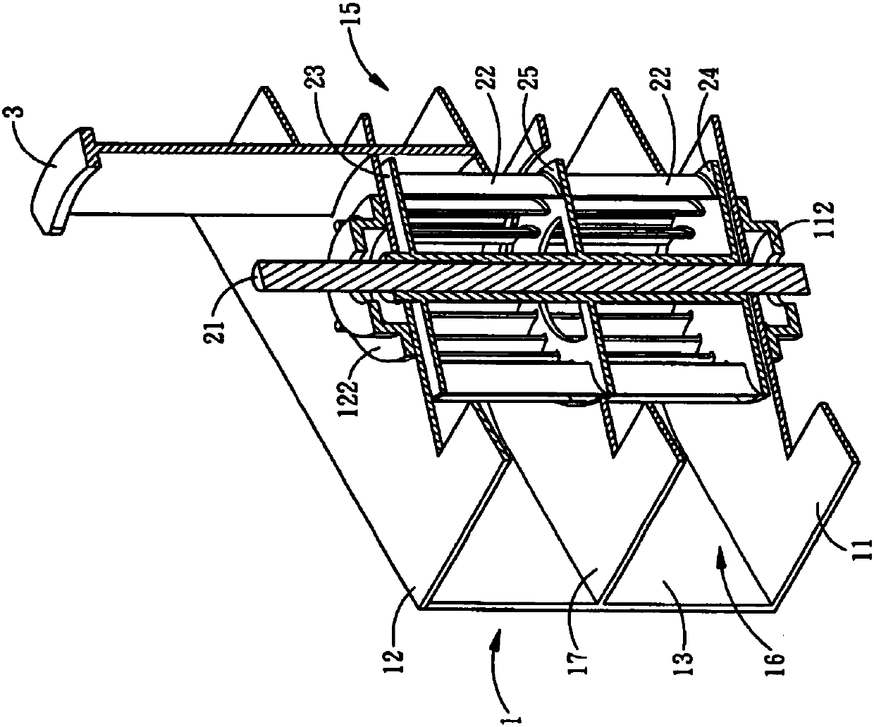
[0042] In order to clearly understand the content of the present invention, only the following descriptions are combined Figure 1 to Figure 6 As shown, the present invention includes a water guide seat 1, a water wheel 2 and a gate piece 3, wherein:

[0043] The middle of the water guide seat 1 is a hollow water wheel room 18. The upstream and downstream sides of the water wheel room 18 are the upstream section 15 and the downstream section 16, respectively. The outermost openings of the upstream section 15 and the downstream section 16 are the water inlet 15a and Outlet 16a;

[0044] The upper and lower sides of the water guide 1 include a bottom plate 11 and a top plate 12. The top plate 12 is separable or partly separable to facilitate the installation of the water wheel 2. The top plate 12 and the bottom plate 11 are respectively provided with a shaft hole 111, 121, A combined bearing set 112, 122 is separately provided to match the installation of the water wheel 2. The top ...


PUM


Abstract

The invention relates to a low-head and high flow water turbine machine.The low-head and high flow water turbine machine comprises a water-guiding base having a top plate, a bottom plate, an accommodating space defined therein, an inlet and an outlet respectively arranged at upstream side and downstream side, and a first and a second lateral plates respectively having a first and a second water-guiding walls that are respectively extending inward toward circumference of the accommodating space, a water turbine arranged in the accommodating space and having multiple blades, and a cylindrical-shaped gate shell passing through the top plate and slidably coupled to circumference of water turbine around upstream side wherein an opening degree is adjusted through sliding the gate shell for adjusting cross-sectional area of stream thereby controlling stream discharge entering to the water turbine, switching off rotation of the water turbine, and adjusting water level at high water level stateat upstream side according to the stream discharge requirement.

Description

Technical field [0001] The invention relates to a vertical axis hydraulic turbine structure with high efficiency with low water head, large flow and flow changes, in particular to a structure that is simple in structure, easy to install and easy to operate, and can be directly assembled in rivers, channels and other places for power generation Low-head large-flow Chuanqu water turbine. Background technique [0002] A water turbine is a device that converts the potential energy of water flow into kinetic energy and then into mechanical energy in a hydroelectric power station. Generally, the most common medium and high-head traditional medium and large hydroelectric power stations are those that concentrate the water flow through a barrage, and then lead the water to the turbine in the plant through the water diversion pipeline, impact the turbine and the turbine, which is driven by the turbine to connect to it. The generator generates electric power, that is, the general traditio...

Claims


Application Information

Patent Timeline
Patent Type & Authority Applications(China)
IPC IPC(8): F03B3/18F03B3/12F03B15/04F03B13/00
CPCF03B13/264F03B15/04F05B2240/13F03B13/08F03B17/063F05B2210/11F05B2240/301F05B2250/231Y02E10/72Y02E10/30Y02E10/20F03B13/10
Inventor 赖融毅
Owner 赖融毅
Why Eureka
Try Eureka