Swing gates for emergency barriers

A barrier and cylinder technology, applied in the field of swing gates for emergency barriers, can solve problems such as unsuitable for moving applications and large overall structure, and achieve the effects of easy handling, increased contact area, and easy disassembly and assembly operations

Active Publication Date: 2019-07-30
CHENGDU ZHIRONG ZHICHUANG INTPROP MANAGEMENT CO LTD
View PDF5 Cites 0 Cited by
  • Summary
  • Abstract
  • Description
  • Claims
  • Application Information

AI Technical Summary

Problems solved by technology

The traditional swing gate has a large overall structure, so it is not suitable for moving applications in some places that temporarily need to limit the flow of people

Method used


Image

  • Swing gates for emergency barriers
  • Swing gates for emergency barriers

Examples


Embodiment 1

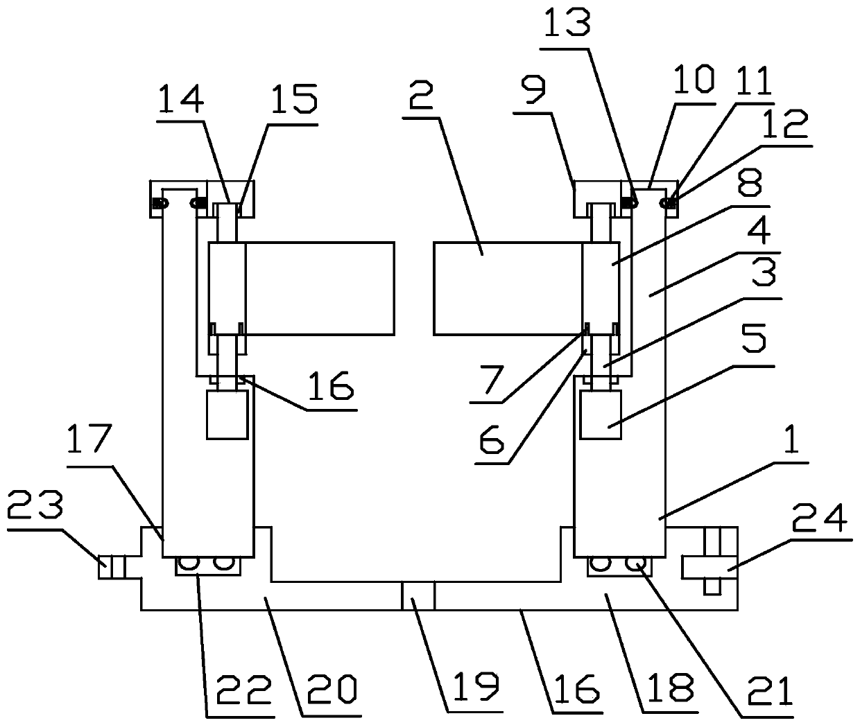
[0032] Such as figure 1 As shown, the present invention provides a swing gate suitable for emergency obstacles, including two cylinders 1 with the same structure and two baffles 2 with the same structure, the axial end of the cylinder 1 is provided with a rotating shaft 3 and a fixed Rod 4, the axial direction of the rotating shaft 3, the axial direction of the fixed rod 4 and the axial direction of the cylinder 1 are parallel; the rotating shaft 3 is driven and rotated by the motor 5 arranged in the cylinder 1, and the rotating shaft 3 is axially at the bottom end side A limit plate 6 is arranged on the wall along the circumferential ring, and a limit bar 7 protrudes upward on the limit plate 6; a connecting sleeve 8 is provided on one side of the baffle plate 2, and the axial bottom of the connecting sleeve 8 The end surface is concavely provided with a limit groove adapted to the limit bar 7, the connecting sleeve 8 is sleeved on the rotating shaft 3, and the limit bar 7 is...

Embodiment 2

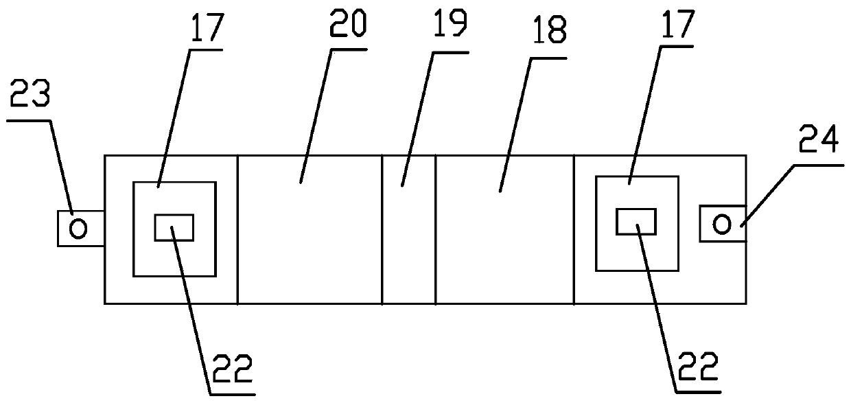
[0034] Further improvement on the basis of Embodiment 1, the base 16 includes a first support plate 18, a transition plate 19 and a second support plate 20 connected end to end in sequence, and the installation groove 17 is provided on the first support plate 18 and the second support plate. The end of the support plate 20 away from the transition plate 19; the first support plate 18 and the transition plate 19 are connected by a hinge, and the transition plate 19 and the second support plate 20 are connected by a hinge.

Embodiment 3

[0036]Further improvement on the basis of Embodiment 2, the axial bottom end surface of the cylinder 1 is provided with a traveling wheel 21 , and the inner bottom of the installation groove 17 is also provided with a traveling wheel groove 22 for accommodating the traveling wheel 21 .


PUM


Abstract

The invention discloses a pendulum brake suitable for an emergency barrier. The pendulum brake suitable for the emergency barrier comprises columns and baffles, wherein a rotary shaft and a fixing rodare arranged on the axial end face of each column, and the rotary shafts are driven by motors in the columns to rotate; a limiting plate is circularly arranged on the side wall of the axial bottom end of each rotary shaft in the circumferential direction, and limiting strips are arranged on the limiting plate in a protruding mode; a connecting sleeve is arranged on one side edge of each baffle, the axial bottom end faces of the connecting sleeves are provided with limiting grooves matched in a concave mode, and the limiting grooves are matched with the limiting strips; the rotary shafts are sleeved with the connecting sleeves; and the limiting strips are embedded in the limiting grooves and fixed in a transition fit mode. The pendulum brake suitable for the emergency barrier further comprises cover plates which are detachably connected with the axial tops of the fixing rods and rotationally connected with the axial tops of the rotary shafts. The pendulum brake suitable for the emergency barrier further comprises a base, the two ends of the base in the long axis direction are each provided with a mounting groove, and the axial bottom ends of the columns are embedded in the mountinggrooves in a transition fit mode. According to the pendulum brake suitable for the emergency barrier, the structure is simple, the main components are detachably connected, assembly and disassembly are convenient, and thus workers can conveniently carry the pendulum brake for storage at any time or move the pendulum brake to a place needing traffic limitation and arrange the pendulum brake quickly.

Description

technical field [0001] The invention relates to a gate machine, in particular to a swing gate suitable for emergency obstacles. Background technique [0002] Swing gates are generally called flapping gates in the rail transit industry. The shape of its blocking body (swing gate) is a plane with a certain area, perpendicular to the ground, and blocking and releasing are realized by rotating and swinging. The material of the arresting body is usually stainless steel, plexiglass, tempered glass, and some also use special flexible materials outsourced with metal plates (to reduce the injury of pedestrians). The traditional swing gate has a large overall structure, and it is not suitable for moving applications in some places that temporarily need to limit the flow of people. Contents of the invention [0003] The purpose of the present invention is to provide a swing gate suitable for emergency obstacles, with a simple structure and detachable connection of the main component...

Claims


Application Information

Patent Timeline
Patent Type & Authority Patents(China)
IPC IPC(8): E01F13/04
CPCE01F13/04
Inventor 徐桥
Owner CHENGDU ZHIRONG ZHICHUANG INTPROP MANAGEMENT CO LTD
Why Eureka
Try Eureka