A monitoring management system and a distribution box
A monitoring management and monitoring control technology, applied in information technology support systems, electrical components, circuit devices, etc., can solve the problems such as the inability to monitor and measure the circuit of the distribution box separately, and the inability to transform and intelligently control the distribution box, so as to achieve remote control. The effect of automatic operation, lower electricity cost and volume reduction
- Summary
- Abstract
- Description
- Claims
- Application Information
AI Technical Summary
Problems solved by technology
Method used
Image
Examples
Embodiment 1
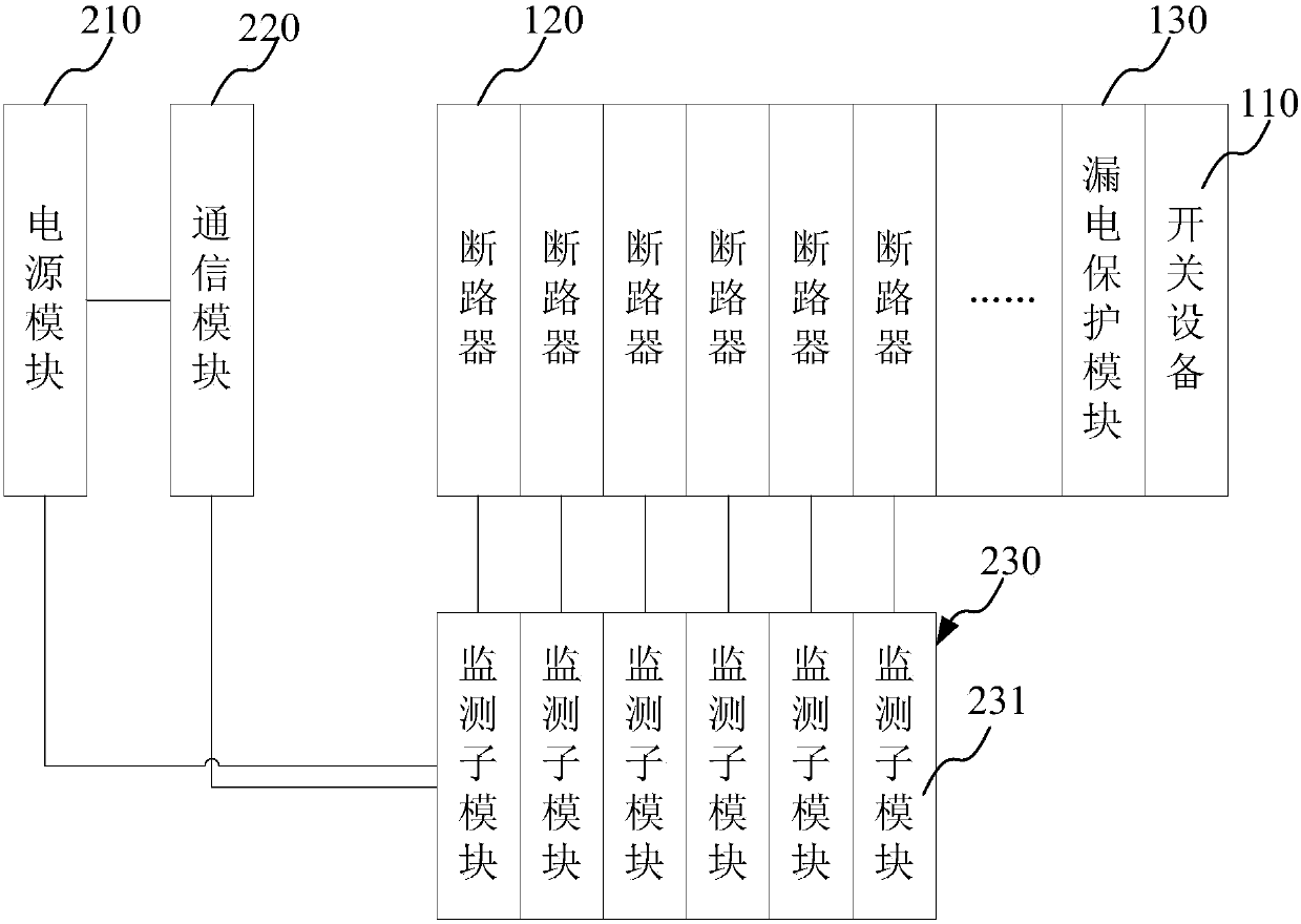
[0042] Such as figure 1 As shown, the monitoring and management system of this embodiment includes: a power supply module 210 , a communication module 220 , and multiple monitoring and control modules 230 . Wherein, the monitoring control module includes a monitoring sub-module 231 .
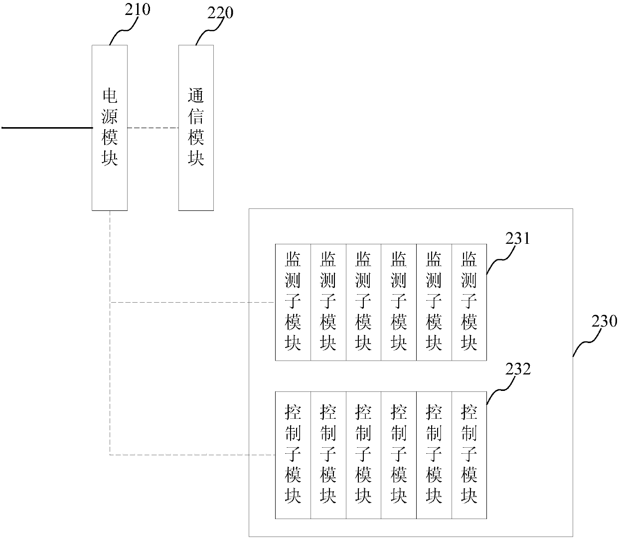
[0043] Wherein, the power supply module 210 is respectively connected with the communication module 220 and the plurality of monitoring sub-modules 231 to provide power for the communication module 220 and the plurality of monitoring sub-modules 231 . The power supply module 210 is fixed at the front end of the distribution box. It takes points from the grid side and provides weak current for the communication module 220 and multiple monitoring sub-modules 231 through AC / DC rectification. For the power supply of the entire monitoring and management system, see figure 2 , where the straight line represents the strong power connected from the grid, and the dotted line represents the weak power ...
Embodiment 2
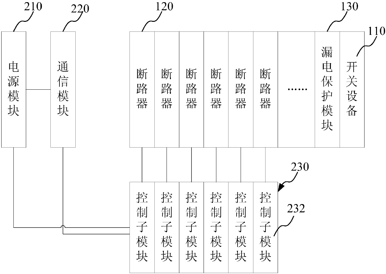
[0054] Such as image 3 As shown, the monitoring management system disclosed in this embodiment is similar in structure to the monitoring management system disclosed in Embodiment 1, but the monitoring control module 230 is slightly different. The monitoring control module 230 of this embodiment only includes the control sub-module 232 .
[0055] The control sub-modules 232 are respectively connected to the power supply module 210 and the communication module 220, and multiple control sub-modules 232 are set corresponding to the circuit breakers 120 of the distribution box, that is, the number of circuit breakers 120 is consistent with the number of control sub-modules 232 of. And the control sub-module 232 is connected in series to the circuit of the corresponding circuit breaker 120 : it can be connected in series to the incoming line end of the corresponding circuit breaker 120 , and can also be connected in series to the outgoing line end of the corresponding circuit brea...
Embodiment 3
[0062] Such as Figure 4 As shown, the monitoring management system disclosed in this embodiment is similar in structure to the monitoring management systems disclosed in Embodiment 1 and Embodiment 2, but the monitoring control module 230 is slightly different. The monitoring control module 230 of this embodiment includes a monitoring submodule 231 and a control submodule 232 .
[0063] The monitoring sub-module 231 and the control sub-module 232 are connected in series with the corresponding circuit breaker 121 . Moreover, the monitoring submodule 231 and the control submodule 232 can be connected in series at one end of the corresponding circuit breaker 121, that is, both the monitoring submodule 231 and the control submodule 232 are connected in series at the incoming / outgoing terminal of the corresponding circuit breaker 120, such as Figure 4 As shown; the monitoring submodule 231 and the control submodule 232 can also be connected in series at both ends of the correspo...
PUM
 Abstract
Description
Claims
Application Information
 - R&D
- Intellectual Property
- Life Sciences
- Materials
- Tech Scout
- Unparalleled Data Quality
- Higher Quality Content
- 60% Fewer Hallucinations
Browse by: Latest US Patents, China's latest patents, Technical Efficacy Thesaurus, Application Domain, Technology Topic, Popular Technical Reports.
© 2025 PatSnap. All rights reserved.Legal|Privacy policy|Modern Slavery Act Transparency Statement|Sitemap|About US| Contact US: help@patsnap.com


