Supercharge Your Innovation With Domain-Expert AI Agents!

Apparatus And Method For The Optical Detection Of Inner Walls

An optical detection and optical imaging technology, which is applied in the direction of using optical devices, measuring devices, and material analysis through optical means, can solve the problems that are not suitable for full-plane 100% detection, and cannot be clearly distinguished from coloring and brightness.

Active Publication Date: 2018-02-02
SAC SIRIUS ADVANCED CYBERNETICS
View PDF13 Cites 4 Cited by
  • Summary
  • Abstract
  • Description
  • Claims
  • Application Information

AI Technical Summary

Problems solved by technology

But this method is based on camera imaging, which cannot clearly distinguish the bumps and depressions relative to the intended geometry from the possible coloring and brightness differences of the material
Other existing methods, although capable of accurate geometrical measurement of smaller cross-sections of cylindrical geometries, are not suitable for full-plane 100% inspection during production

Method used


Image

  • Apparatus And Method For The Optical Detection Of Inner Walls
  • Apparatus And Method For The Optical Detection Of Inner Walls
  • Apparatus And Method For The Optical Detection Of Inner Walls

Examples


Embodiment Construction

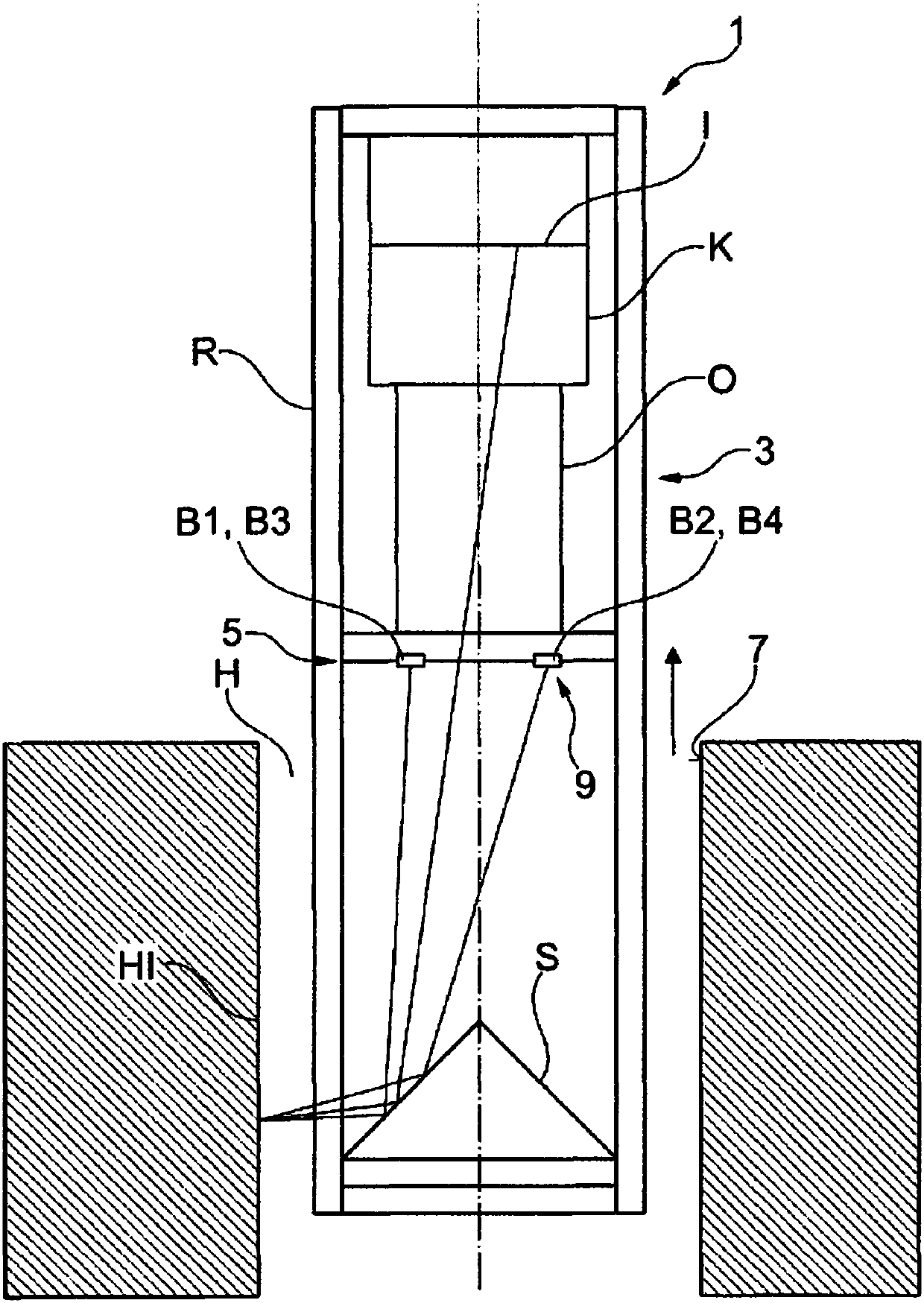
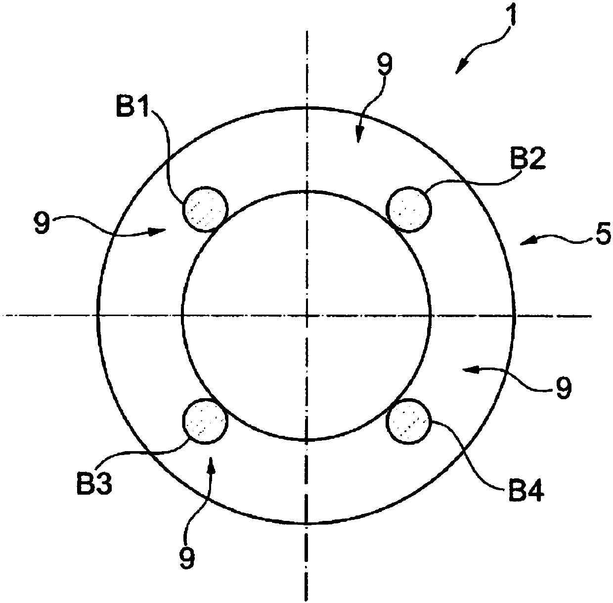
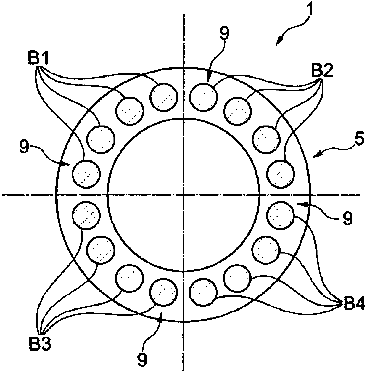
[0059] figure 1 Shows a side view of a device 1 comprising a camera K, an imaging device 3 with a camera objective O and a conical mirror S, and an illumination device 5 with n=4 light sources 9, also called illuminators B1, B2 , ... all the way to Bn. In the example shown, the conical mirror S has an opening angle of 90°. Furthermore the device 1 comprises a cylindrical tube R which houses the aforementioned optical elements and which is transparent in at least one region, preferably in the region where the illumination light path and / or the observation light path pass. Preferably the entire device 1, hereinafter also referred to as arrangement, is first inserted into the borehole or cavity H by means of a device not shown in the figure until the desired position is reached, and then further in the direction of the arrow Back to sports. Cameras can optionally be performed during insertion and / or removal of the borehole. The imaging is preferably carried out during removal...


PUM


Abstract

An apparatus (1) for the optical detection of inner walls (7) is proposed, comprising - at least one camera (K), - an optical imaging arrangement (3), and - an illumination arrangement (5), wherein -the apparatus (1) is configured to record in a panoramic view by means of the camera (K) a plurality of regions of an inner wall (7) which are axially offset from one another. The apparatus (1) is distinguished by virtue of the illumination arrangement (5) having at least two different functional states, wherein a first brightness distribution emitted by the illumination arrangement (5) is assigned to a first functional state, said brightness distribution differing from a second brightness distribution in at least one second functional state.

Description

technical field [0001] The invention relates to a device and a method for the optical detection of inner walls, in particular to the optical interior measurement and / or shape measurement of cavities, especially boreholes. The wall of the cylindrical borehole and in particular the wall of the cylindrical borehole of the combustion engine is thereby detected and / or measured in shape. In particular, 100% real-time control of the drilling process is achieved hereby. Background technique [0002] Existing methods probe the entire surface of the borehole wall. However, this method is based on camera imaging, which cannot clearly distinguish elevations and depressions relative to the desired geometry from possible coloring and brightness differences of the material. Other existing methods, although capable of accurate geometrical measurement of smaller cross-sections of cylindrical geometries, are not suitable for full-plane 100% inspection during production. Contents of the in...

Claims


Application Information

Patent Timeline
IPC IPC(8): G01B11/25G01B11/30G01N21/954G01B11/12
CPCG01B11/12G01B11/2518G01B11/2527G01B11/306G01N21/954G01N2021/9544G01N2021/9548G01N2201/0635G01B11/24G01N2201/061
Inventor 克里斯托弗·瓦格纳
Owner SAC SIRIUS ADVANCED CYBERNETICS
Features
  • R&D
  • Intellectual Property
  • Life Sciences
  • Materials
  • Tech Scout
  • Unparalleled Data Quality
  • Higher Quality Content
  • 60% Fewer Hallucinations
Learn More