Aircraft engine fuel nozzle precision piece grinding quick-change tooling and using method

A technology for aero-engine and fuel nozzles, applied in the direction of grinding workpiece supports, grinding/polishing equipment, grinding machines, etc., can solve the problems of small structure and size of aero-engine fuel nozzles, difficult operation, poor product size consistency, etc., to avoid The effect of many times of grinding and clamping, ensuring safe operation and reducing the difficulty of work

Active Publication Date: 2018-02-09
AECC AVIATION POWER CO LTD
View PDF7 Cites 3 Cited by
  • Summary
  • Abstract
  • Description
  • Claims
  • Application Information

AI Technical Summary

Problems solved by technology

[0003] Optical curve grinders are usually used to grind the shape of aero-engine fuel nozzles. Due to the limitation of the shape and inner cavity structure, when grinding the shape, there is no place for direct clamping on the aero-engine fuel nozzle. At present, only the traditional "Double top" structure clamping, or "one clamping one top" mode clamping with the help of shape clamping for changing datum
[0004] However, in actual processing, due to the small structure size, complex shape and high precision requirements of the aero-engine fuel nozzle, it is necessary to repeatedly disassemble and assemble the parts many times when grinding on the optical curve grinder to adjust the size or grind different parts. The "double top" structure or the "one clamp and one top" method of changing the reference by means of external clamping is inconvenient for disassembly and assembly, and the error after the second clamping is large, and the product size consistency is poor, which seriously affects the processing quality of the precision parts of the nozzle. At the same time, During grinding, the grinding wheel and the workpiece are prone to interference. The operator needs to be highly vigilant during grinding to prevent overcutting, which makes the operation difficult.

Method used


Image

  • Aircraft engine fuel nozzle precision piece grinding quick-change tooling and using method
  • Aircraft engine fuel nozzle precision piece grinding quick-change tooling and using method
  • Aircraft engine fuel nozzle precision piece grinding quick-change tooling and using method

Examples


Embodiment Construction

[0032] The present invention will be further described in detail below in conjunction with specific embodiments, which are explanations of the present invention rather than limitations.

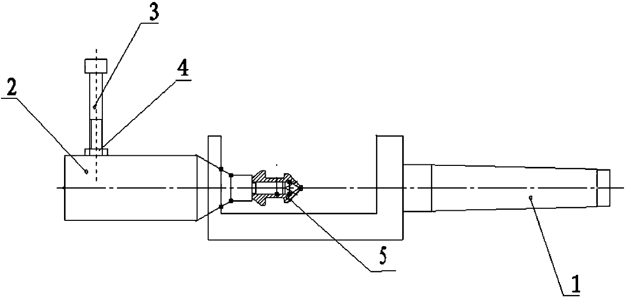
[0033] Such as figure 1 As shown, a quick-change tool for grinding precision parts of an aero-engine fuel nozzle includes an adapter shaft 1, a positioning mandrel 2 and a fork screw assembly; one end of the adapter shaft 1 is tapered, and the other end is provided with a U-shaped groove, The side of the U-shaped groove away from the tapered end is provided with a mounting hole for the positioning mandrel 2; one end of the positioning mandrel 2 is provided with a connector, which is used to connect the precision part 5 of the fuel nozzle of the aero-engine, and the positioning mandrel 2 is provided with The connection part of the adapter shaft 1 is installed in the installation hole of the positioning mandrel 2, and the other end of the positioning mandrel 2 is provided with a positioning tip...


PUM


Abstract

The invention discloses aircraft engine fuel nozzle precision piece grinding quick-change tooling and a using method, and belongs to the technical field of quick-change tooling. The quick-change tooling includes a rotating connecting shaft, a positioning mandrel and a shifting fork screw assembly. An aircraft engine fuel nozzle precision piece to be ground is mounted on the positioning mandrel, and the positioning mandrel and the rotating connecting shaft are connected with and mounted on a grinding machine, so that the fact that quick mounting and clamping of the aircraft engine fuel nozzle precision piece are changed is achieved, the problems that grinding, mounting and clamping of the shape of the aircraft engine fuel nozzle precision piece are high in frequency and low in precision aresolved, repeated centering in the process of mounting and clamping is omitted, the working difficulty of grinding operators is reduced, the production efficiency, machining accuracy and size consistency of the nozzle precision piece are improved, and the running safety of an aircraft engine is ensured.

Description

technical field [0001] The invention belongs to the technical field of quick-change tooling, in particular to a quick-change tooling for grinding precision parts of an aero-engine fuel nozzle and a use method thereof. Background technique [0002] The fuel nozzle of aero-engine is one of the important parts of aero-engine, and its processing quality has an important influence on the performance of aero-engine. The structure of an aero-engine fuel nozzle is relatively complex, and its exterior usually includes a suspended cone section, a flange section, a groove section, a matching cylinder section, an oil-flowing cone section, and an oil-flowing cylinder section. Among them, the taper, diameter and Roughness requirements are different. In order to meet the requirements of use, it is usually necessary to grind the shape of aero-engine fuel nozzles. [0003] The shape of the fuel nozzle of the aero-engine is usually ground by using an optical curve grinder. Due to the limitat...

Claims


Application Information

Patent Timeline
Patent Type & Authority Applications(China)
IPC IPC(8): B24B19/00B24B41/06
CPCB24B19/00B24B41/06
Inventor 张立义韩新艳冯锦丽刘点席丽娜董少锋吕阿鹏刘振峰
Owner AECC AVIATION POWER CO LTD
Why Eureka
Try Eureka