Fabricated steel structure beam-column connection joint and connection method thereof

A technology of beam-column connection and steel structure, which is applied in the direction of building structure and construction, can solve the problems of poor shock absorption effect, poor friction effect, limited friction force, etc., and achieve the effect of avoiding brittle fracture problems

Active Publication Date: 2018-02-09
江苏承天新型建材有限公司
View PDF6 Cites 18 Cited by
  • Summary
  • Abstract
  • Description
  • Claims
  • Application Information

AI Technical Summary

Problems solved by technology

In practical application, the friction force generated by the steel plates in the overlapping area is limited. In particular, during the vibration process, the loosening of the bolts is inevitable. After the bolts are loosened, the friction effect will be reduced sharply, so this kind of The structure is also uncontrollable, and relative to the kinetic energy generated by the earthquake, the friction effect is poor and the shock absorption effect is poor

Method used


Image

  • Fabricated steel structure beam-column connection joint and connection method thereof
  • Fabricated steel structure beam-column connection joint and connection method thereof
  • Fabricated steel structure beam-column connection joint and connection method thereof

Examples


Embodiment Construction

[0041] The present invention will be described in detail below in conjunction with the accompanying drawings.

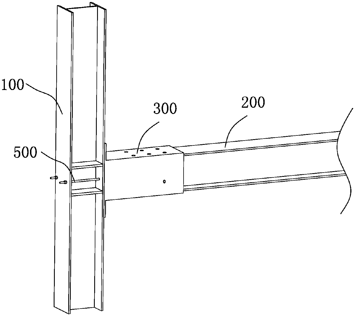
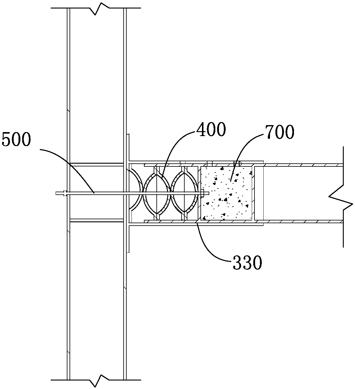
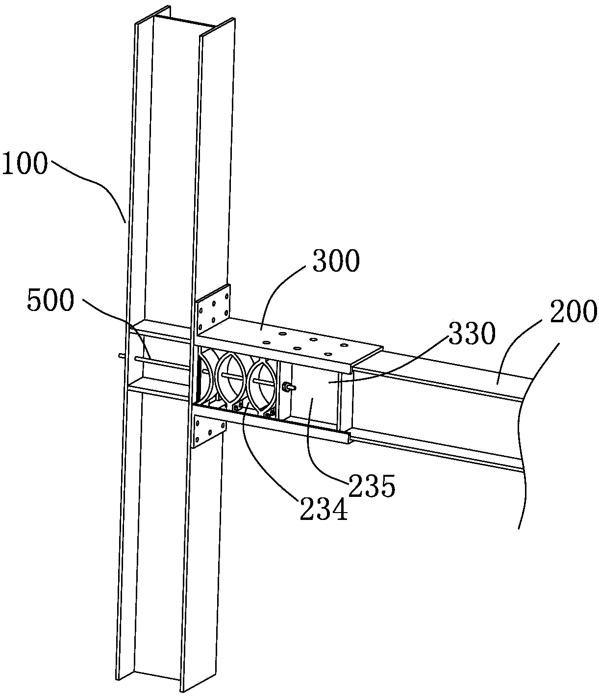
[0042] Assembled steel structure beam-column connection node is suitable for the connection of steel beams and steel columns. The steel column mentioned in the present invention refers to a steel column that is usually in a vertical state or close to a vertical state. It is mainly based on the ground, and the inclined ones are also slightly inclined, usually with an angle of no more than 15 degrees. The steel girder here is usually in a horizontal state in steel structure buildings.

[0043] The steel beams and steel columns here only include I-shaped steel materials commonly used in steel structures, and other structures, such as square steel and channel steel, are not within the scope of the present invention.

[0044] Based on the research of I-steel beams and steel columns, I-steel has good torsion resistance and bending resistance, and saves steel, so it is wid...


PUM


Abstract

The invention discloses a fabricated steel structure beam-column connection joint and a connection method thereof. The fabricated steel structure beam-column connection joint is used for solving the problem that an existing joint is poor in anti-seismic performance and for connection of a steel beam and a steel column. The end of the steel beam is a connection part, and a set of plate-shaped spring assemblies is arranged in each of mounting grooves on the two sides of the steel beam. A concrete block formed by grouting is arranged in a grouting space between a grouting trough and the inner wall of a rectangular steel pipe. A transition connection part is composed of a steel plate and the rectangular steep pipe, wherein the steel plate is fixed to the steel beam through a high-strength bolt, a plug-in part is formed in the rectangular steel pipe, and the connection part is inserted into the plug-in part to form partial overlapping. Anchor pulling holes are formed in the plate-shaped spring assemblies, a separation plate and the steel column, after a steel cable penetrates through the anchor pulling holes, the two ends of the steel cable are fixed to the steel column and the steel beam correspondingly. Under a non-seismic state, the joint is rigid connection, under a seismic state, movable flexible connection is formed, and thus the problem of fragile fracturing brought by the rigid joint can be avoided.

Description

technical field [0001] The invention relates to the technical field of fabricated steel structures. Background technique [0002] In the field of prefabricated steel structure technology, steel structure nodes need to be connected by prefabricated connection. The traditional connection method refers to Figure 9 The structure shown in , that is, L-shaped connectors are used for excessive connection between steel beams and steel columns, where L-shaped connectors and steel columns are connected by high-strength bolts, and L-shaped connectors and steel beams are connected by high-strength bolts Strength bolts for connection. The main problem with this structure is that the seismic performance is not good, and when a strong earthquake occurs, brittle fractures are likely to occur at the connecting parts. [0003] In order to solve the seismic problem of the connection joints of steel beams and steel columns, experts and scholars at home and abroad have carried out a large numb...

Claims


Application Information

Patent Timeline
Patent Type & Authority Applications(China)
IPC IPC(8): E04B1/24E04B1/58
CPCE04B1/2403E04B2001/2415E04B2001/2421
Inventor 孔金河
Owner 江苏承天新型建材有限公司
Why Eureka
Try Eureka