Gas stove with lifting type dry-boiling prevention temperature sensors and control method thereof

A technology of temperature sensor and gas cooker, which is applied in the control of the above-mentioned gas cooker and the field of gas cooker, can solve the problems of small contact pressure, small contact area, prone to skewed contact between the temperature sensor and the bottom of the pot, etc., and achieve simple control, The effect of the simple control method

Inactive Publication Date: 2018-02-09
GUANGDONG MIDEA KITCHEN APPLIANCES MFG CO LTD +1
View PDF8 Cites 13 Cited by
  • Summary
  • Abstract
  • Description
  • Claims
  • Application Information

AI Technical Summary

Problems solved by technology

[0003] However, the current control of the rise and fall of the temperature sensor is usually complicated and not intelligent enough
In addition, the rising stroke of the temperature sensor is not effectively controlled, so that the gas stove also has the following defects: (1) The bottom of some pots 8 is concave, so that the compression amount of the spring is too small, and the contact pressure is small, causing the interface Large thermal resistance is not conducive to rapid heat transfer, resulting in large temperature measurement errors; (2) when the rising stroke is insufficient, the pot 8 with a concave bottom of some pots cannot be in contact with the temperature sensor, such as figure 1 As shown; when the rising stroke is too large, the pot 8 protruding from the bottom of some pots is supported by the temperature sensor and cannot be placed stably, as figure 2 (3) In order to make a good contact between the bottom of the pot and the temperature sensor, the bottom of the pot must be in parallel contact with the temperature sensor and pressed down vertically during the process of putting the pot, otherwise the temperature sensor and the bottom of the pot will easily have skewed contact , resulting in a smaller contact area and a larger error in temperature measurement, such as image 3 shown

Method used


Image

  • Gas stove with lifting type dry-boiling prevention temperature sensors and control method thereof
  • Gas stove with lifting type dry-boiling prevention temperature sensors and control method thereof
  • Gas stove with lifting type dry-boiling prevention temperature sensors and control method thereof

Examples


Embodiment 1

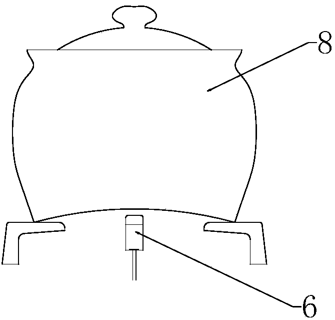
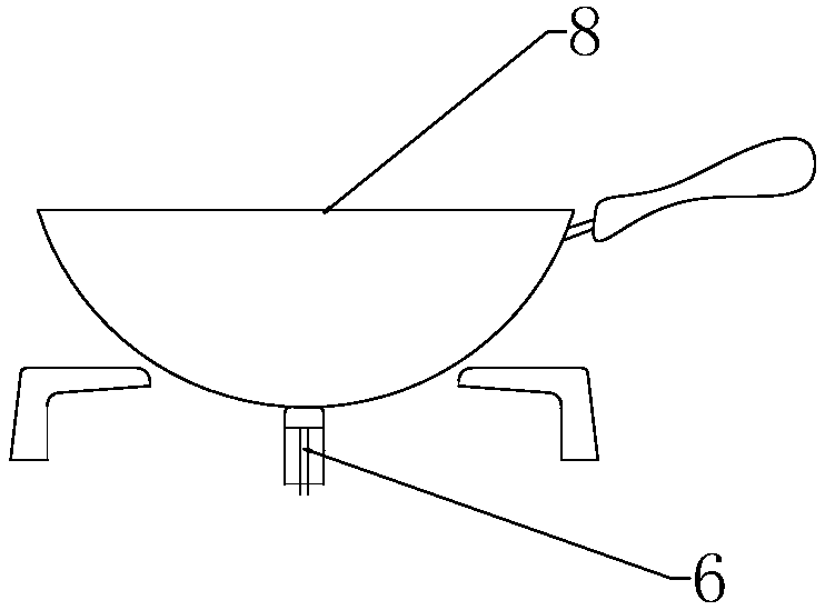
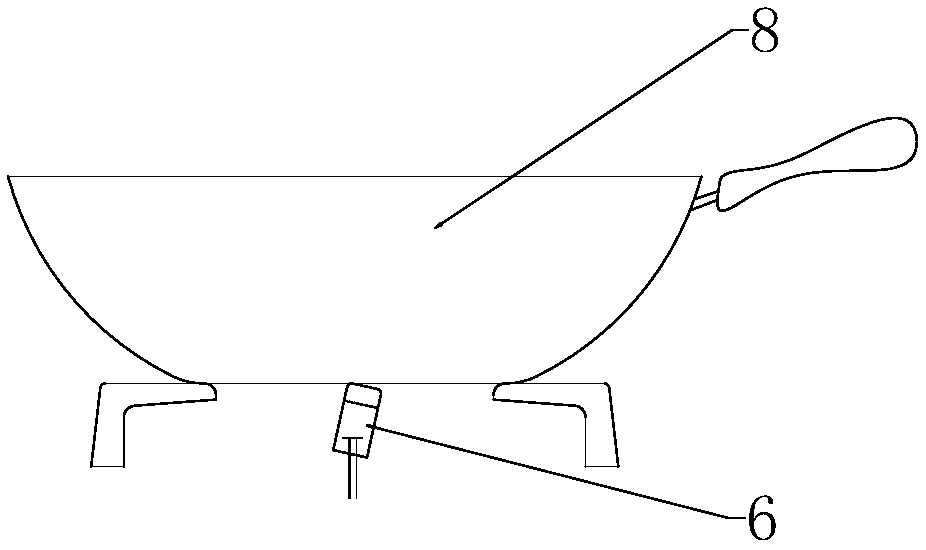
[0052] Figure 4 to Figure 11 A preferred embodiment of a gas cooker with a lift-type anti-dry heating temperature sensor according to the present invention is shown. As shown in the figure, the gas stove includes a panel 3, a burner 2, a pot support 1, and the burner 2 also includes a fire cover with a central through hole and a temperature sensor 6 arranged in the central through hole of the fire cover. Wherein the fire cover can be one circle or multiple circles (single or multiple). The gas cooker also includes a lift mechanism 7 connected with the temperature sensor 6 for driving the temperature sensor up and down, and a control system connected with the lift mechanism 7 for controlling the lift of the temperature sensor 6 . When the gas cooker is not working, the temperature sensor 6 can be lowered into the inside of the cooker through the central through hole of the fire cover through the lifting mechanism under the control of the control system, such as Figure 7 sho...

Embodiment 2

[0093] This embodiment is basically the same as Embodiment 1. For the sake of brevity, in the description process of this embodiment, the same technical features as Embodiment 1 will not be described, and only the differences between this embodiment and Embodiment 1 will be described:

[0094] Such as Figure 12 with Figure 13As shown, the judging device includes a limit switch 65 arranged on the inner tube 61, and a sensitive block 68 is arranged on the wire 67. When the elastic element 64 reaches a predetermined amount of compression, the sensitive block 68 on the wire 67 and the limit switch 68 Correspondingly, and trigger the limit switch 68. That is to say, when the lifting mechanism 7 drives the temperature sensor 6 to rise and fall, the limit switch 68 rises and falls together with the temperature sensor 6, and when the temperature sensor 6 touches the pot 8 during the rising process, the outer end cover stops rising, and the inner pipe 61 As it continues to rise, th...

Embodiment 3

[0106] This embodiment is basically the same as Embodiment 1. For the sake of brevity, in the description process of this embodiment, the same technical features as Embodiment 1 will not be described, and only the differences between this embodiment and Embodiment 1 will be described:

[0107] Such as Figure 15 As shown, the lifting mechanism 7C includes a fixed bracket 7C-1 for fixing the temperature sensor 6, a cam 7C-2 and a support frame 7C-5 for supporting the cam 7C-2, the fixed bracket 7C-1 includes a fixed bracket body, One side of the fixed bracket body is provided with a transverse chute 7C-8, and the free end of the cam 7C-2 is slidably connected with the transverse chute 7C-8.

[0108] During use, the cam 7C-2 is rotated, and the fixed bracket 7C-1 cooperating with the cam 7C-2 is driven to move up and down under the rotation of the cam 7C-2, thereby driving the temperature sensor 6 connected with the fixed bracket 7C-1 to move up and down, so , the lifting mecha...


PUM


Abstract

The invention relates to the technical field of kitchen appliances, in particular to a gas stove with lifting type dry-boiling prevention temperature sensors and a control method thereof. The gas stove comprises the temperature sensors, a lifting mechanism connected with the corresponding temperature sensors and used for driving the temperature sensors to rise and all and a control system connected with the lifting mechanism and used for controlling the temperature sensors to rise and fall. The gas stove further comprises weight sensors used for acquiring weight information. The control systemis connected with the weight sensors. By means of the gas stove and the control method thereof provided by the invention, the weight information of cookware is collected through the weight sensors; the gas stove judges whether the lifting mechanism needs to rise or not according to the collected weight information of the cookware. Accordingly, intelligent rising and falling of the temperature sensors are achieved, and control is simple and reliable.

Description

technical field [0001] The invention relates to the technical field of kitchen appliances, in particular to a gas stove with a lift-type anti-dry-burning temperature sensor, and a control method for the gas stove. Background technique [0002] At present, gas stoves with anti-dry function are provided with a temperature sensor in the center of the burner to detect the temperature of the bottom of the pot 8 . When the temperature detected by the temperature sensor reaches the preset value, it is judged as dry burning, and the work of the cooker is stopped, so as to realize the function of preventing dry burning of the cooker. Usually, when the gas cooker is working, the temperature sensor can be lifted out from the central through hole of the fire cover 5 under the drive of the lifting mechanism and contact with the bottom of the pot 8; driven down into the inside of the cooker to protect the temperature sensor. [0003] However, the current control of the rise and fall of ...

Claims


Application Information

Patent Timeline
Patent Type & Authority Applications(China)
IPC IPC(8): F24C3/12F24C15/10
CPCF24C3/126F24C15/107
Inventor 李国韩杰季俊生余悦泳
Owner GUANGDONG MIDEA KITCHEN APPLIANCES MFG CO LTD
Why Eureka
Try Eureka