Automatic lifting type off-road vehicle front cabin luggage bracket system and control method

A front cabin, off-road vehicle technology, applied in vehicle parts, transportation and packaging, etc., can solve problems such as hidden safety hazards, inconvenience in taking luggage, and difficulty in taking luggage, so as to improve the user experience and prevent accidental ejection.

Active Publication Date: 2022-03-01
DONGFENG MOTOR GRP
View PDF7 Cites 1 Cited by
  • Summary
  • Abstract
  • Description
  • Claims
  • Application Information

AI Technical Summary

Problems solved by technology

[0003] However, when used in a pure electric off-road vehicle, due to the high chassis of the pure electric off-road vehicle, it will be difficult for smaller users to take luggage from the luggage compartment in the front cabin , it is very inconvenient to take luggage manually by using steps and tools, and there are potential safety hazards

Method used


Image

  • Automatic lifting type off-road vehicle front cabin luggage bracket system and control method
  • Automatic lifting type off-road vehicle front cabin luggage bracket system and control method
  • Automatic lifting type off-road vehicle front cabin luggage bracket system and control method

Examples


Embodiment 1

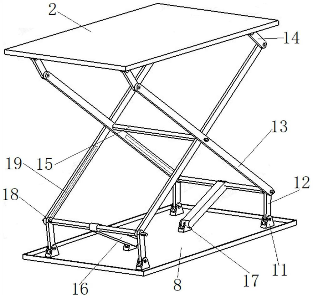
[0047] Embodiment one, such as figure 2 As shown, the lifting mechanism 9 specifically includes: a support 11 , a support rod 12 , a lifting rod 13 , an adjustment rod 14 , an intermediate rod 15 , a driving rod 16 , a driving motor 17 , a slider 18 and a chute 19 .

[0048] Described support 11 is provided with four and is fixed on the upper surface of base 8 in rectangular shape, specifically can be bolted; A lift bar 13 is hinged;

[0049] Wherein, the two lifting rods 13 near the outside of the front nacelle intersect each other and are hinged at their intersection A, and the two lifting rods 13 near the inside of the front nacelle cross each other and are hinged at their intersection B, and the intersection A and An intermediate rod 15 is connected between the intersection points B;

[0050] One end of each lifting rod 13 away from the support rod 12 is hinged with an adjusting rod 14, and the end of the adjusting rod 14 away from the lifting rod 13 is hinged with the ...

Embodiment 2

[0055] Embodiment 2, the principle and technical solution of this embodiment are basically the same as Embodiment 1, the difference is that: the drive rod 16 is a hydraulic telescopic rod, and the two ends of the drive rod 16 are hinged to the lift rod 13, so The forward rotation and reverse rotation of the driving motor 17 respectively drive the hydraulic telescopic rod to shorten and extend, and then drive the two intersecting lifting rods 13 to approach and move away from each other through the hinge movement, so as to realize the rise and fall of the luggage tray 2 .

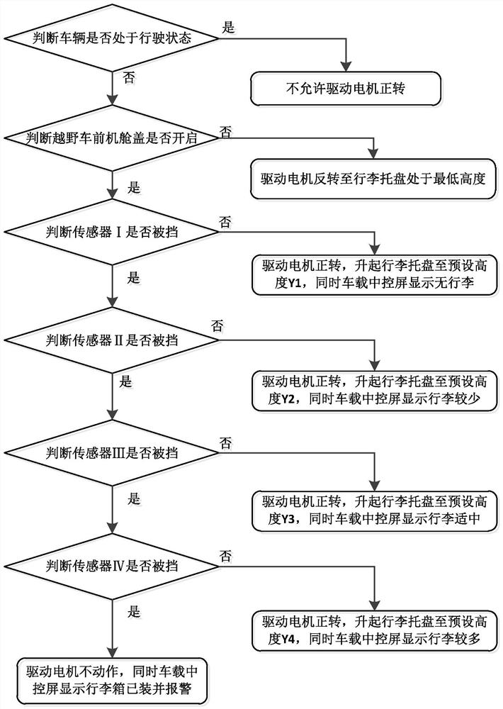
[0056] 3. A control method for the front cabin luggage rack system of an automatic lifting off-road vehicle

[0057] Based on the same inventive concept, the embodiment of the present application also provides a control method for the front cabin luggage rack system of an automatic lifting off-road vehicle, based on the above-mentioned front cabin luggage rack system, such as image 3 As shown, it specifical...


PUM


Abstract

The invention relates to the technical field of automobile luggage brackets, in particular to an automatic lifting type off-road vehicle front cabin luggage bracket system and a control method. A base, a lifting mechanism and a luggage tray are arranged in a trunk of a front cabin of a pure electric off-road vehicle, the height of loaded luggage is collected through a sensor, control is conducted in cooperation with a bracket controller, intelligent lifting of the luggage tray can be achieved, and a client can conveniently take and place the luggage; the bracket controller is connected with the vehicle-mounted central control screen and all the sensors, the vehicle working condition and the luggage taking intention of a client are intelligently judged, the height of the trunk tray is automatically adjusted by combining the height of the loaded luggage, the use experience of the client is improved, and meanwhile the situation that the trunk pops up mistakenly in the driving process, and driving safety is affected is prevented.

Description

technical field [0001] The invention relates to the technical field of automobile luggage racks, in particular to an automatic lifting off-road vehicle front cabin luggage rack system and a control method. Background technique [0002] Since pure electric vehicles do not have an engine, the drive system is a motor, and the motor system generally takes up much less space than the engine system. Therefore, after the motor system is arranged in the front cabin of a traditional electric vehicle, enough space is reserved for the front. The design of the cabin luggage. [0003] However, when used in a pure electric off-road vehicle, due to the high chassis of the pure electric off-road vehicle, it will be difficult for smaller users to take luggage from the front cabin luggage compartment. They must use steps and tools, and it is very inconvenient to take luggage manually by traditional methods. , and there are security risks. Contents of the invention [0004] The technical p...

Claims


Application Information

Patent Timeline
Patent Type & Authority Applications(China)
IPC IPC(8): B60R5/02
CPCB60R5/02
Inventor 宋瀚王国进周松涛杨玄龙梁海杰
Owner DONGFENG MOTOR GRP
Why Eureka
Try Eureka