

Antenna switching method, communication terminal and computer readable storage medium
An antenna switching and communication terminal technology, which is applied in the field of communication, can solve the problems such as reduced transceiver performance of mobile terminals and low user experience, so as to achieve reliable and effective switching and improve user experience.
- Summary
- Abstract
- Description
- Claims
- Application Information
AI Technical Summary
Problems solved by technology
Method used
Image

Examples
no. 1 example
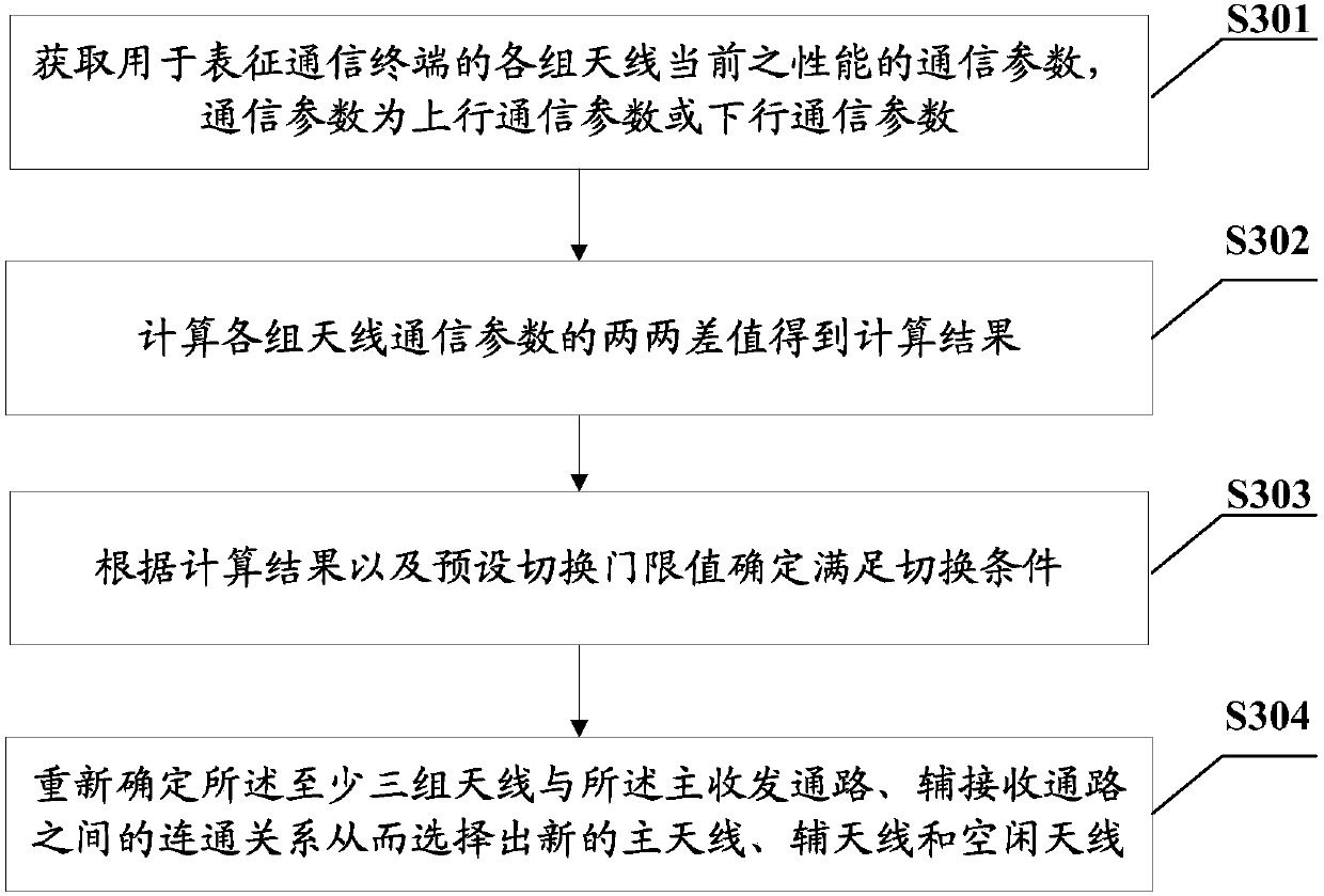
[0073] In order to solve the problem in the prior art that the working role of the antenna in the terminal is fixed, so that the receiving and transmitting performance of the terminal is easily affected by factors such as the user's holding posture, thus making the communication performance of the terminal unstable, this embodiment provides an antenna switching method. The antenna switching method is mainly applied to a communication terminal including at least three groups of antennas, among the at least three groups of antennas, the main antenna that is currently connected to the main transceiver channel, the auxiliary antenna that is currently connected to the auxiliary transceiver channel, and the remaining antennas are idle antennas. For the flow chart of the antenna switching method provided in this embodiment, please refer to image 3 shown, including:
[0074] S301: Obtain communication parameters used to characterize the current performance of each group of antennas o...
no. 2 example
[0096] In this embodiment, the positions of the antennas of each group in the communication terminal in the foregoing embodiments are described first. See Figure 4 As shown, three groups of antennas are set on the communication terminal,
[0097] The first antenna group 41 is arranged on the top thereof, and the second antenna group 42 and the third antenna group 43 are respectively arranged on the left and right sides of the bottom of the terminal. Since the roles of "main antenna", "auxiliary antenna" and "idle antenna" in this embodiment are interchangeable, at a certain moment, the first antenna group 41 may be used as the main antenna, while the second antenna group 42 may be used as the main antenna. It works as an auxiliary antenna, while the third antenna group 43 does not work temporarily. At another moment, it may become that the second antenna group 42 and the third antenna group 43 are respectively used as the main antenna and the auxiliary antenna to participat...
example 1
[0100] Assume that only one communication parameter is obtained, and in this example, it is assumed that the obtained communication parameter is the received signal strength. See Figure 6 as shown, Figure 6 Schematic flow chart of the antenna switching method provided for this example, including:
[0101] S601: Obtain the current received signal strength of each antenna of the communication terminal.
[0102] Assume that after collecting the current received signal strength parameters of each antenna, it is determined that the current main antenna, auxiliary antenna and idle antenna, that is, the signal strengths of A, B and C are -52dBm, -56dBm and -60dBm respectively.
[0103] S602: Calculate pairwise difference values of received signal strengths of each antenna.
[0104] In this example, by d AB Characterize the pairwise difference between antenna A and antenna B, similarly, by d BC and d AC Respectively characterize the pairwise difference between antenna B and ...
PUM
 Abstract
Description
Claims
Application Information