Transition mode pfc power converter adapted to switch from dcm to ccm under high load and control method

a power converter and high load technology, applied in power conversion systems, climate sustainability, energy industry, etc., can solve the problems of complex control circuitry, current ripple of amplitude that is about twice the value of the waveform of the average current, etc., and achieve the effect of reliable and efficient switching

Active Publication Date: 2015-01-01
STMICROELECTRONICS INT NV
View PDF11 Cites 31 Cited by
  • Summary
  • Abstract
  • Description
  • Claims
  • Application Information

AI Technical Summary

Benefits of technology

[0009]An effective, though much simplified control method for reliably and efficiently switching a from DCM to CCM a transition mode (TM) power factor corrector (PFC) power converter is highly desired.

Problems solved by technology

This is due to the fact that the transition mode peculiarity of requiring a nullification of the current in the inductor at every switching cycle has the drawback of producing a current ripple of amplitude that is about twice the value of the waveform of the average current.
The ability to switch from a DCM (discontinuous current mode) to a CCM (continuous current mode) under high load conditions generally requires a complex control circuitry, given that the common technique, based on an on-time control timer of the switch of the boost inductor, relies on a null initial current for obtaining a current proportional to the instantaneous input voltage and thus is unsuitable.

Method used


Image

  • Transition mode pfc power converter adapted to switch from dcm to ccm under high load and control method
  • Transition mode pfc power converter adapted to switch from dcm to ccm under high load and control method
  • Transition mode pfc power converter adapted to switch from dcm to ccm under high load and control method

Examples


Embodiment Construction

[0030]The following description has the purpose of illustrating the general principles of the disclosure being claimed and should not be taken in a limiting sense. The scope of the disclosure is best determined by reference to the appended claims.

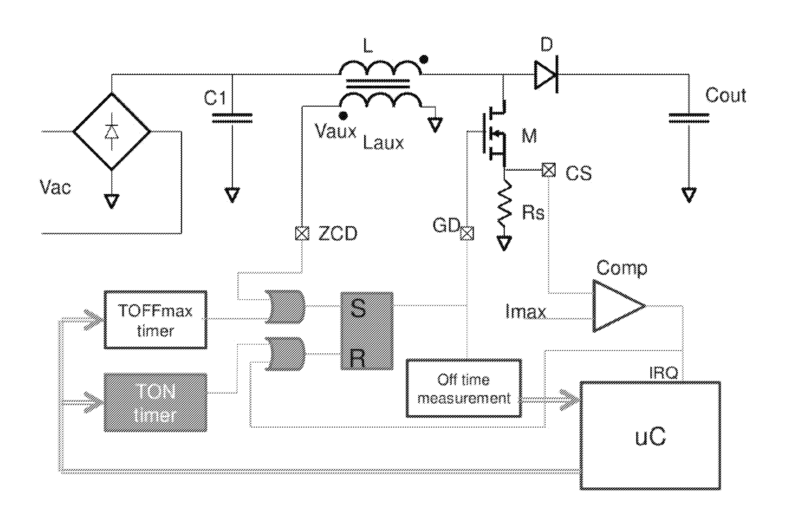
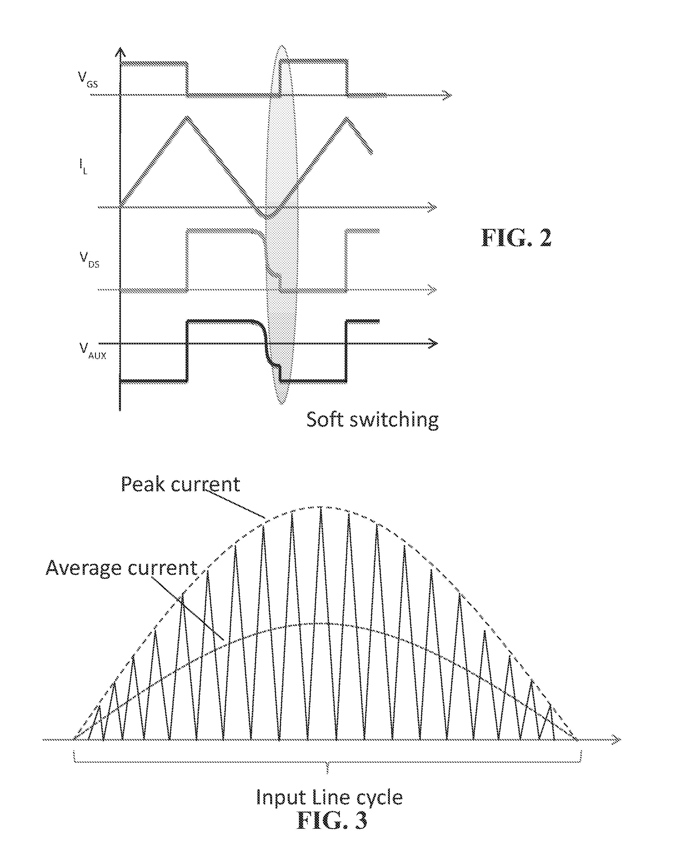
[0031]The peculiar aspects of this disclosure are here after described for the case of one of common PFC circuit configurations though the characteristic features of the disclosure that will be described may be embodied in any other PFC circuit configuration commonly being used by adapting, in the described exemplified manner, the control circuit of the transition mode (TM) power factor corrector (PFC) power converter to make it switch from a DCM (discontinuous current mode) to a CCM (continuous current mode) under heavy load.

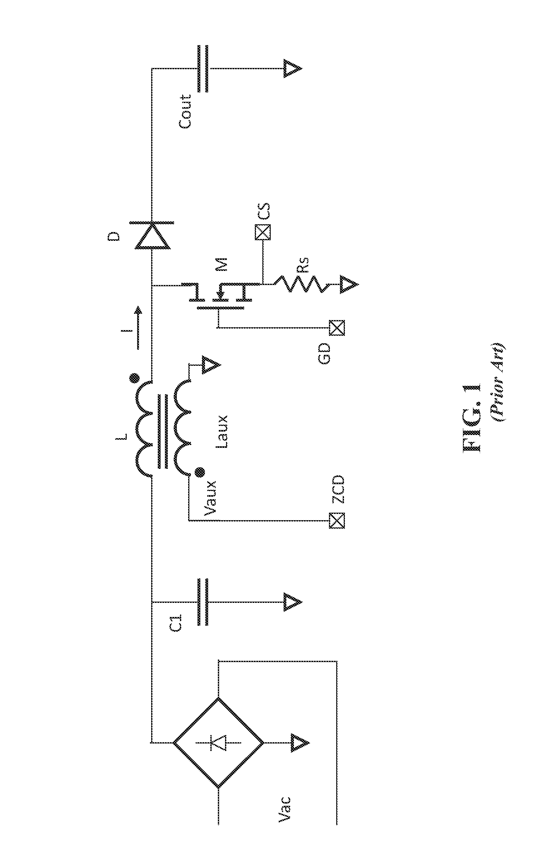
[0032]Basically, a common example as depicted in FIG. 1, a transition mode (TM) power factor correction device comprises a boost inductor L, a switch M, a diode D, an output tank capacitor Cout and a zero crossing dete...


PUM


Abstract

A transition mode power factor correction converter comprising a boost inductor, a switch, a diode, and output tank capacitor, has circuit means of limitation of the off-time interval of the switch to a fraction of the off-time interval, “complementary” to the on-time interval that is normally controlled for regulating the output voltage, during part of a cycle of a rectified sinusoidal voltage waveform input to the converter, when the current flowing in the inductor reaches a maximum threshold, causing the mode of operation of the device to switch from transition mode to continuous current mode for a middle phase angle region of a rectified sinusoidal input voltage waveform, under high load conditions, defined by said maximum current threshold. Current peaks amplitude and ripple are effectively reduced for same output power.

Description

BACKGROUND[0001]1. Technical Field[0002]The disclosure relates to a transition mode (TM) power factor corrector (PFC) power converter adapted to switch from a DCM (discontinuous current mode) to a CCM (continuous current mode) under high load.[0003]2. Description of the Related Art[0004]Transition mode (also known as quasi resonant) boost power factor corrector devices (PFC) function in a discontinuous current mode (DCM) and have a high efficiency. However, for a same average current value, in DCM the power transfer current reaches higher peak values of than in a switching power converter functioning in a continuous current mode (CCM). This is due to the fact that the transition mode peculiarity of requiring a nullification of the current in the inductor at every switching cycle has the drawback of producing a current ripple of amplitude that is about twice the value of the waveform of the average current.[0005]In a PFC (power factor correction) power converter there is a current lo...

Claims


Application Information

Patent Timeline
Patent Type & Authority Applications(United States)
IPC IPC(8): H02M1/42
CPCH02M1/4225Y02B70/126H02M1/4208Y02B70/10Y02P80/10
Inventor BIANCO, ALBERTO
Owner STMICROELECTRONICS INT NV
Why Eureka
Try Eureka