Antenna switching trigger control method, communication terminal and computer readable storage medium

An antenna switching and triggering control technology, applied in the field of communications, can solve the problems of inability to perform effective switching, improve performance, poor user experience, etc., and achieve the effect of reliable and effective switching, good performance, and improved user experience.

Inactive Publication Date: 2017-12-12
NUBIA TECHNOLOGY CO LTD
View PDF7 Cites 24 Cited by
  • Summary
  • Abstract
  • Description
  • Claims
  • Application Information

AI Technical Summary

Problems solved by technology

[0006] The technical problem to be solved by the present invention is: the main antenna of the exis

Method used


Image

  • Antenna switching trigger control method, communication terminal and computer readable storage medium
  • Antenna switching trigger control method, communication terminal and computer readable storage medium
  • Antenna switching trigger control method, communication terminal and computer readable storage medium

Examples


Example

[0066] First embodiment

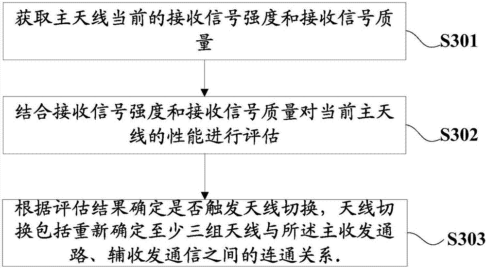
[0067] In order to solve the problem that the current performance of the main antenna is degraded due to various factors (for example, being blocked by the user's palm), the effective switching cannot be performed to improve the performance, and the user experience is poor. This embodiment provides an antenna switching trigger control method. See image 3 , image 3 The basic flowchart of the antenna switching trigger control method provided in this embodiment, the antenna switching trigger control method includes:

[0068] S301: Acquire the current received signal strength and received signal quality of the main antenna.

[0069] The main transceiver path in this embodiment can be a definite communication path, which has been set and determined before leaving the factory. It is used for information communication between the connected antenna and the internal communication system of the mobile phone. It can be connected to any antenna, and at least Among th...

Example

[0092] Second embodiment

[0093] In order to better understand the present invention, this embodiment combines specific examples under the GSM network standard to provide a specific method for judging whether to trigger antenna switching based on the received signal strength indicator of the main antenna and the signal-to-noise ratio. Please refer to Figure 5 , Figure 5 This is a detailed flowchart of the notification message prompting method provided by the second embodiment of the present invention. The antenna switching trigger control method includes:

[0094] S501: Acquire the current received signal strength indication and signal-to-noise ratio of the main antenna.

[0095] The communication terminal obtains the received signal strength and received signal quality of the main antenna at a certain time. Under the GSM network standard, it also obtains the received signal strength indicator P of the main antenna. 0 And signal-to-noise ratio Q 0 .

[0096] S502: When it is determi...

Example

[0106] The third embodiment

[0107] This embodiment also provides a communication terminal, see Image 6 As shown, it includes a processor 601, a memory 602, a communication bus 603, a communication unit 604, and an antenna 605;

[0108] The communication bus 603 is used to implement connection and communication between the processor 601, the memory 602, and the communication unit 604;

[0109] The communication unit 604 may be a radio frequency communication unit (radio frequency circuit), or other types of communication units, which include a main transceiver path and an auxiliary receiving path (not shown in the path diagram). The antenna 605 includes at least three groups. Among the group antennas, the main antenna that is currently connected to the main transceiver path is the auxiliary antenna, the antenna that is currently connected to the auxiliary receiving path is the auxiliary antenna, and the rest are idle antennas.

[0110] The memory 602 is configured to execute one or ...


PUM


Abstract

The invention discloses an antenna switching trigger control method. The method is applied to a communication terminal that consists of a main transceiver channel, an auxiliary receiving channel and at least three sets of antennae, the antennae communicated to the main transceiver channel are main antennae, the antennae communicated to the auxiliary receiving channel are auxiliary antennae, and the remaining antennae are idle antennae. The method comprises the following steps: acquiring the received signal strength and received signal quality of the current main antennae of the communication terminal, evaluating the performance of the current main antennae in combination with the received signal strength and received signal quality, and determining whether to trigger antenna switching according to an evaluation result. The invention also discloses the communication terminal and a computer readable storage medium. By storing programs with the above functions and implementing the above scheme through a processor, the problem that the main antennae cannot perform effective switching to improve the performance when the current performance is reduced due to various factors, and the use experience of users is poor in the prior art can be solved.

Description

technical field [0001] The present invention relates to the technical field of communication, and more specifically, to a trigger control method for antenna switching, a communication terminal and a computer-readable storage medium. Background technique [0002] With the development of terminal technology, the functions of mobile terminals are becoming more and more comprehensive, and the services it provides to users are becoming more and more perfect. At its simplest, mobile terminals have derived services in many aspects, such as taking pictures, surfing the Internet, and playing audio / video, from the pure call and text message functions in the past. However, although mobile terminals currently have a wide variety of functions, and with the development of technology, there will still be more and more intelligent functions that will spring up like mushrooms in future terminals, but the communication functions carried by mobile terminals will still be used as One of the mo...

Claims


Application Information

Patent Timeline
IPC IPC(8): H04B1/401H04B17/318H04B17/336H04M1/725
CPCH04B1/401H04B17/318H04B17/336H04M1/72454
Inventor 汪重庆
Owner NUBIA TECHNOLOGY CO LTD
Why Eureka
Try Eureka