Thin layer prediction method and device

A prediction method and thin layer technology, applied in the field of petroleum seismic exploration, can solve the problems of low prediction accuracy and large error, and achieve the effect of solving the low prediction accuracy

Active Publication Date: 2018-02-13
BC P INC CHINA NAT PETROLEUM CORP +1
3 Cites 2 Cited by

AI-Extracted Technical Summary

Problems solved by technology

[0005] The implementation mode of this application provides a thin-layer prediction method and device to solve ...

Method used

From the above description, it can be seen that the thin layer prediction method provided by the embodiment of the present application; by setting up wave impedance models and tuning modes according to the geological characteristics of different wave impedance types, the target layer is adjusted by the corresponding tuning mode Therefore, the technical problems of low prediction accuracy and large error in the existing methods are solved, and different wave impedances can be analyzed. According to the technical effect of thin layer tuning effect analysis and thin layer prediction; and according to the logging data, the wave impedance type corresponding to the target layer is identified, and the accurate identification of the wave impedance type of the target layer is achieved. .
[0138] From the above description, it can be seen that the thin layer prediction device provided by the embodiment of the p...

Abstract

The invention provides a thin layer prediction method and a device, wherein the method includes that log data and seismic data of a target layer are obtained; wave impedance type of the target layer is obtained according to the log data; a corresponding wave impedance model is established according to the wave impedance type; a corresponding tuning model is ensured according to the wave impedancemodel; the thin layer prediction is conducted according to the tuning model and the seismic data. The corresponding wave impedance type of the target layer is distinguished through the seismic data, and then the corresponding wave impedance model and the tuning model is ensured according to the different wave impedance types, which can make the thin layer prediction more accurately. So the existing technical problems of low accuracy and large error in the thin layer prediction are solved. And the technical effect of tuning effect analysis and thin layer prediction can be achieved for differenttypes of the wave impedance thin layer.

Application Domain

Seismic signal processing

Technology Topic

Wave impedanceThin layer +4

Image

  • Thin layer prediction method and device
  • Thin layer prediction method and device
  • Thin layer prediction method and device

Examples

  • Experimental program(1)

Example Embodiment

[0066] In order to enable those skilled in the art to better understand the technical solutions in the present application, the technical solutions in the embodiments of the present application will be clearly and completely described below in conjunction with the drawings in the embodiments of the present application. Obviously, the described The embodiments are only some of the embodiments of the present application, but not all of them. Based on the embodiments in this application, all other embodiments obtained by persons of ordinary skill in the art without creative efforts shall fall within the scope of protection of this application.
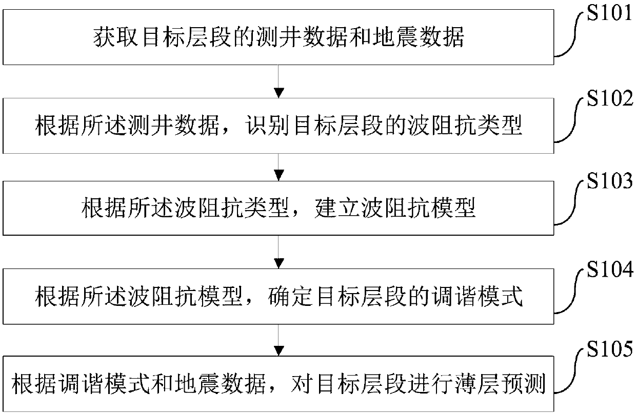
[0067] Considering the existing thin layer prediction methods, because the characteristics of different wave impedance types are not analyzed, the corresponding tuning effect analysis and thin layer prediction are not carried out for layers of different wave impedance types, but the same wave impedance is applied The method corresponding to the type performs specific thin-layer tuning effect analysis and specific thin-layer prediction, resulting in technical problems such as low prediction accuracy and large errors in specific implementation. In view of the root cause of the above technical problems, this application considers that the specific wave impedance type of the target layer can be determined before the thin layer prediction, and the thin layer tuning effect analysis is carried out by using the corresponding tuning effect analysis method according to different wave impedance types , and then use the corresponding thin layer prediction method to carry out specific thin layer prediction. In this way, the technical problems of low prediction accuracy and large errors in the existing thin layer prediction methods are solved, and the technical effect of targeted tuning effect analysis and thin layer prediction for different wave impedance types of thin layers is achieved.
[0068] Based on the thinking above, the embodiments of the present application provide a thin layer prediction method. see figure 1 The processing flowchart of the thin layer prediction method provided according to the embodiment of the present application. The thin-layer prediction method provided in the embodiments of the present application may specifically include the following steps.
[0069] In this embodiment, the thin layer may specifically include but not limited to a reservoir layer or a caprock. Therefore, predicting the thin layer of the target interval through the thin layer prediction method provided in the present application can realize the prediction of the reservoir of the target interval, and can also realize the prediction of the caprock of the target interval and so on.
[0070] Step S101: Obtain well logging data and seismic data of the target interval.
[0071] In this embodiment, the well logging data may specifically be the well logging data of known wells on the target interval, and the above well logging data are usually relatively clear. During specific implementation, the wave impedance type corresponding to the target interval can be identified according to the above logging data. Then, for the wave impedance class corresponding to the target interval, according to the seismic data, the thin layer tuning effect analysis and specific thin layer prediction can be carried out.
[0072] Step S102: Identify the wave impedance type of the target interval according to the logging data.
[0073] In this embodiment, in order to more accurately identify the wave impedance type of the target interval, specific implementation may be performed in the following manner.
[0074] S102-1: Establish a wave impedance curve according to the logging data.
[0075] In this embodiment, in order to establish the above-mentioned wave impedance curve, the following steps may be followed during specific implementation.
[0076] S102-1-1: Obtain an acoustic (AC) curve and a density (DEN) curve from the logging data.
[0077] S102-1-2: Establish a wave impedance curve according to the acoustic wave curve and the density curve.
[0078] In one embodiment, in order to establish the wave impedance curve, during specific implementation, the above wave impedance curve can be established according to the following formula according to the above-mentioned acoustic wave curve and the above-mentioned density curve:
[0079]
[0080] In the above formula, AI is the wave impedance, AC is the acoustic time difference logging data value, and DEN is the measured density value of the logging curve.
[0081] S102-2: Perform modeling processing on the wave impedance curve to obtain a processed wave impedance curve.
[0082] In one embodiment, in order to facilitate subsequent identification of the wave impedance type of the target interval, the wave impedance curve may be modeled first to obtain the wave impedance curve after processing. During specific implementation, the aforementioned modeling processing of the wave impedance curve may include: performing mean value filtering on the wave impedance curve, and/or performing extreme value filtering on the wave impedance curve. In this embodiment, it should be noted that, when the overall wave impedance curve is relatively stable with no or only a small amount of sudden changes, it may be preferable to carry out specific modeling processing on the wave impedance curve through extremum filtering. In the case where the wave impedance curve contains many abrupt changes, it may be preferable to carry out specific modeling processing on the above wave impedance curve by mean filtering.
[0083] S102-3: Identify the wave impedance type of the target interval according to the processed wave impedance curve.
[0084] In this embodiment, according to the processed wave impedance curve, the geological characteristics reflected by the wave impedance curve can be obtained, that is, the change characteristics of wave impedance with depth in the logging data, and the target interval can be identified according to the geological characteristics. Corresponding wave impedance type. Among them, the above-mentioned wave impedance types can specifically include: the first type, that is, the "high envelope and low" type: the wave impedance value of the middle layer is small, and the wave impedance values ​​of the top and bottom layers are large; the second type, that is, the "low envelope and high" type : The wave impedance value of the middle layer is large, and the wave impedance value of the top and bottom layers is small; the third type: "gradual change type": the wave impedance value gradually decreases from the bottom layer, through the middle layer, to the top layer.
[0085] Step S103: Establish a wave impedance model according to the wave impedance type.
[0086] In this embodiment, in order to establish corresponding wave impedance models according to different wave impedance types, so as to perform subsequent thin-layer tuning analysis more accurately, in specific implementation, according to the wave impedance types, Establish the corresponding wave impedance model.
[0087] S103-1: When the wave impedance type is the first type, establish a first wave impedance model, wherein the wave impedance of the top layer and the wave impedance of the bottom layer of the first wave impedance model are greater than the wave impedance of the middle layer .
[0088] S103-2: When the wave impedance type is the second type, establish a second wave impedance model, wherein the wave impedance of the top layer and the wave impedance of the bottom layer of the second wave impedance model are smaller than the wave impedance of the middle layer .
[0089] S103-3: When the wave impedance type is the third type, establish a third wave impedance model, wherein the wave impedance of the bottom layer of the third wave impedance model is greater than the wave impedance of the middle layer, and the wave impedance of the middle layer The wave impedance is greater than that of the top layer.
[0090] Step S104: Determine the tuning mode of the target interval according to the wave impedance model.
[0091] In one embodiment, in order to determine the tuning mode of the corresponding target interval by using different wave impedance models, the following steps may be followed in specific implementation.
[0092] S104-1: Determine a plurality of synthetic seismic records through model forward modeling according to multiple preset frequencies of the Lake wavelet and the wave impedance model.
[0093] In one embodiment, considering various situations that may arise, in order to perform subsequent tuning effect analysis more accurately, this embodiment proposes that multiple Reyker wavelets with different preset frequencies can be used to determine multiple corresponding synthetic Earthquake records. During specific implementation, model forward modeling is carried out according to the following formula to determine each synthetic seismic record in the plurality of synthetic seismic records:
[0094] x(t)=W(t)*R(t)
[0095] In the above formula, x(t) is the synthetic seismic record, W(t) is the Reker wavelet, R(t) is the reflection coefficient, and the value is determined according to the wave impedance model.
[0096] In one embodiment, the above-mentioned reflection coefficient can be specifically determined according to the wave impedance model of the target layer section. During specific implementation, the corresponding reflection coefficient can be determined according to the following formula:
[0097]
[0098] In the above formula, AI 2 is the wave impedance value of the bottom layer of the wave impedance model, AI 1 is the wave impedance value of the top layer of the wave impedance model.
[0099]In one embodiment, the multiple preset frequencies of Reyker wavelets may be three different frequencies of Reyker wavelets. Specifically, the first type of Reyker wavelet with a preset frequency may be a Reyker wavelet with a frequency between 10HZ and 20HZ, preferably a Reyker wavelet with a preset frequency of 15HZ. The second type of Reyker wavelet with a preset frequency may be a Reyker wavelet with a frequency between 20HZ and 50HZ, preferably a Reyker wavelet with a preset frequency of 30HZ. The third kind of Reyker wavelet with a preset frequency may be a Reyker wavelet with a frequency between 50HZ and 70HZ, preferably a Reyker wavelet with a preset frequency of 60HZ. Of course, it should be noted that the rake wavelets of various preset frequencies listed above are only for better illustration of this embodiment. The Kelet wave is used as the Reyker wavelet of the above-mentioned various preset frequencies.
[0100] S104-2: Obtain the amplitude value of the top reflection of the middle layer of each synthetic seismic record in the plurality of synthetic seismic records, and the reflection time thickness between the top and the bottom of the middle layer of each synthetic seismic record.
[0101] S104-3: According to the amplitude value of the top reflection of the middle layer of the synthetic seismic record and the reflection time thickness between the top and the bottom of the middle layer of the synthetic seismic record, create a cross map.
[0102] S104-4: Determine the tuning mode of the target interval according to the intersection map.
[0103] In this embodiment, during specific implementation, the tuning mode corresponding to the target interval can be determined according to the geological characteristics reflected in the intersection diagram, and then the targeted thin layer tuning can be performed on the target interval according to the determined tuning mode Effect analysis.
[0104] In one embodiment, in order to determine the tuning mode corresponding to the target interval according to the intersection graph, specific implementation may be performed in the following manner.
[0105] According to the intersection diagram, with the increase of the seismic reflection amplitude in the intersection diagram with the formation thickness, the tuning mode of the target interval that first increases and then decreases is determined as the first tuning mode; the seismic reflection amplitude in the intersection diagram is With the increase of the formation thickness, it first decreases and then increases, and the tuning mode of the target interval whose seismic reflection amplitude is negative is determined as the second tuning mode; the seismic reflection amplitude in the intersection diagram increases with the formation thickness, first decreases The tuning mode of the target interval that is small and then increases is determined as the third tuning mode.
[0106] In one embodiment, the tuning mode of the target interval may specifically be one of the following: a first tuning mode, a second tuning mode, and a third tuning mode. Wherein, the first tuning mode takes the point where the amplitude value is positive and the absolute value of the amplitude value is the maximum value as the tuning point, and the second tuning mode takes the point where the amplitude value is negative and the absolute value of the amplitude value is the maximum value The point of is the tuning point, and in the third tuning mode, the point where the amplitude value is positive and the absolute value of the amplitude value is the minimum value is the tuning point. During specific implementation, specific thin layer tuning effect analysis can be carried out according to the seismic data of the target interval and in combination with the corresponding tuning mode.
[0107] Step S105: Perform thin layer prediction on the target interval according to the tuning mode and the seismic data.
[0108] In one embodiment, in order to perform targeted thin layer prediction on the target interval more accurately, during specific implementation, the target interval can be calculated according to the tuning mode and the seismic data in the following manner: Specific TLC predictions.
[0109] S105-1: In the case that the tuning mode of the target interval is the first tuning mode, according to the seismic data, determine the tuning body, and obtain the frequency corresponding to the maximum energy in the tuning body as the tuning frequency, according to The tuning frequency is used to perform thin layer prediction on the target interval; or, through frequency division inversion, to perform thin layer prediction on the target interval.
[0110] S105-2: When the tuning mode of the target interval is the second tuning mode, according to the seismic data, determine the tuning body, and obtain the frequency corresponding to the maximum energy in the tuning body as the tuning frequency, according to The tuning frequency is used to perform thin layer prediction on the target interval; or, through frequency division inversion, to perform thin layer prediction on the target interval.
[0111] S105-3: In the case that the tuning mode of the target interval is the third tuning mode, according to the seismic data, determine the tuning body, and obtain the frequency corresponding to the energy minimum value in the tuning body as the tuning frequency, according to The tuning frequency is used to perform thin layer prediction on the target interval.
[0112] In one embodiment, in order to perform thin layer prediction on the target interval according to the tuning frequency, specific implementation may include the following content: quantitatively determine the thin layer thickness of the target interval according to the tuning frequency, and calculate If the thin layer thickness of the target interval is taken out, it can be considered that the determination of the thin layer of the target interval has been realized.
[0113] In one embodiment, in order to determine the thickness of the thin layer, during specific implementation, the thickness of the above thin layer can be determined according to the following formula:
[0114]
[0115] In the above formula, h is the thickness of the thin layer, v is the layer velocity of the target interval, wherein the layer velocity of the target interval can be determined according to the logging acoustic time difference curve (acoustic wave curve), f 0 for the determined tuning frequency.
[0116] In one embodiment, in order to predict the thin layer, the thin layer prediction may also be performed on the target interval through frequency division inversion. Wherein, the above-mentioned frequency division inversion can also be regarded as a kind of wave impedance inversion. During specific implementation, the thin layer prediction of the target interval through frequency-division inversion may include: using the seismic data to perform frequency-division inversion to obtain a tuning body; according to the tuning body, determine a tuning amplitude slice; According to the tuned amplitude slice, the plane distribution law is determined; and the thin layer prediction is performed by using the plane distribution law. In this embodiment, it needs to be explained that during specific implementation, the thin layer prediction can be carried out through wave impedance inversion alone or through frequency division inversion alone according to the specific situation and specific construction requirements; it can also be combined with wave impedance inversion and frequency-division inversion for thin layer prediction. In this regard, this application does not make a limitation.
[0117] From the above description, it can be seen that the thin layer prediction method provided by the embodiment of the present application; through the establishment of wave impedance models and tuning modes according to the geological characteristics of different wave impedance types, the target layer section can be specifically tuned through the corresponding tuning mode. Therefore, the technical problems of low prediction accuracy and large error in the existing methods are solved, and the thin layer of different wave impedance types can be analyzed. Carry out targeted thin layer tuning effect analysis and technical effect of thin layer prediction; and identify the wave impedance type corresponding to the target layer according to the logging data, and achieve accurate identification of the wave impedance type of the target layer.
[0118] Based on the same inventive concept, the embodiments of the present invention also provide a thin-layer prediction device, as described in the following embodiments. Since the problem-solving principle of the device is similar to that of the thin-layer prediction method, the implementation of the thin-layer prediction device can refer to the implementation of the thin-layer prediction method, and the repetition will not be repeated. As used below, the term "unit" or "module" may be a combination of software and/or hardware that realizes a predetermined function. Although the devices described in the following embodiments are preferably implemented in software, implementations in hardware, or a combination of software and hardware are also possible and contemplated. see figure 2 , is a structural diagram of the thin layer prediction device according to the embodiment of the present application. The device may include: an acquisition module 201, an identification module 202, an establishment module 203, a determination module 204, and a prediction module 205. The following details the structure illustrate.
[0119] The acquisition module 201 can specifically be used to acquire well logging data and seismic data of the target interval.
[0120] The identifying module 202 may specifically be configured to identify the wave impedance type of the target interval according to the logging data.
[0121] The establishment module 203 may be specifically configured to establish a wave impedance model according to the wave impedance type.
[0122] The determination module 204 may specifically be configured to determine the tuning mode of the target interval according to the wave impedance model.
[0123] The prediction module 205 can be specifically configured to perform thin layer prediction on the target interval according to the tuning mode and the seismic data.
[0124] In one embodiment, in order to more accurately identify the wave impedance type of the target interval according to the logging data, the identification module 202 may specifically include:
[0125] The first establishing unit can be specifically configured to establish a wave impedance curve according to the logging data;
[0126] The processing unit may specifically be used to perform modeling processing on the wave impedance curve to obtain a processed wave impedance curve;
[0127] The identification unit may specifically be configured to identify the wave impedance type of the target interval according to the processed wave impedance curve.
[0128] In one embodiment, in order to establish corresponding wave impedance models according to different wave impedance types through the establishment module 203, during specific implementation, the establishment module 203 may establish the first wave impedance type when the wave impedance type is the first type. A wave impedance model, wherein the wave impedance of the top layer and the bottom layer of the first wave impedance model are greater than the wave impedance of the middle layer; the second wave impedance can be established when the wave impedance type is the second type Impedance model, wherein, the wave impedance of the top layer and the wave impedance of the bottom layer of the second wave impedance model are smaller than the wave impedance of the middle layer; the third wave impedance model can be established when the wave impedance type is the third type , wherein the wave impedance of the bottom layer of the third wave impedance model is greater than that of the middle layer, and the wave impedance of the middle layer is greater than that of the top layer.
[0129] In one embodiment, in order to more accurately determine the tuning mode of the target interval according to the wave impedance model, the determination module 204 may specifically include:
[0130] The first determination unit may be specifically configured to determine a plurality of synthetic seismic records through model forward modeling according to the Reich wavelets of various preset frequencies and the wave impedance model;
[0131] The acquisition unit may be specifically configured to acquire the amplitude value of the top reflection of the middle layer of each synthetic seismic record in the plurality of synthetic seismic records, and the reflection time thickness between the top and bottom of the middle layer of each synthetic seismic record;
[0132] The second building unit may be specifically configured to create a cross-graph according to the amplitude value of the top reflection of the middle layer of the synthetic seismic record and the reflection time thickness between the top and the bottom of the middle layer of the synthetic seismic record;
[0133] The second determination unit may specifically be configured to determine the tuning mode of the target interval according to the intersection graph.
[0134]In one embodiment, in order to enable the prediction module 205 to perform corresponding thin layer prediction on the target interval according to different tuning modes and in combination with the seismic data of the target interval. During specific implementation, the prediction module 205 can determine the tuning body according to the seismic data when the tuning mode of the target interval is the first tuning mode, and obtain the frequency corresponding to the maximum energy in the tuning body as Tuning frequency, according to the tuning frequency, perform thin layer prediction on the target interval; or, through frequency division inversion, perform thin layer prediction on the target interval; the tuning mode in the target interval is the second tuning In the case of the mode, according to the seismic data, determine the tuning body, and obtain the frequency corresponding to the energy maximum value in the tuning body as the tuning frequency, and perform thin layer prediction on the target interval according to the tuning frequency; or, by Frequency-division inversion, performing thin layer prediction on the target interval; in the case that the tuning mode of the target interval is the third tuning mode, according to the seismic data, determine the tuning volume, and obtain the tuning volume The frequency corresponding to the minimum value of the medium energy is used as the tuning frequency, and thin layer prediction is performed on the target interval according to the tuning frequency.
[0135] Each embodiment in this specification is described in a progressive manner, the same and similar parts of each embodiment can be referred to each other, and each embodiment focuses on the differences from other embodiments. In particular, for the system embodiment, since it is basically similar to the method embodiment, the description is relatively simple, and for relevant parts, refer to part of the description of the method embodiment.
[0136] It should be noted that the systems, devices, modules or units described in the above embodiments may be implemented by computer chips or entities, or by products with certain functions. For the convenience of description, in this specification, when describing the above devices, the functions are divided into various units and described respectively. Of course, when implementing the present application, the functions of each unit can be implemented in one or more pieces of software and/or hardware.
[0137] Furthermore, in this specification, adjectives such as first and second may only be used to distinguish one element or action from another without necessarily requiring or implying any actual such relationship or order. Reference to an element or component or step (etc.) should not be construed as being limited to only one of the element, component, or step, but may be one or more of the element, component, or step, etc., where the circumstances permit.
[0138] From the above description, it can be seen that the thin layer prediction device provided by the embodiment of the present application establishes corresponding wave impedance models and tuning modes according to the geological characteristics of different wave impedance types through the establishment module and determination module, and through the corresponding tuning The model conducts specific tuning effect analysis on the target interval, and then can use the prediction module to carry out specific thin layer prediction in a corresponding way. Therefore, it solves the technical problems of low prediction accuracy and large errors in the existing methods , to achieve the technical effects of thin layer tuning effect analysis and thin layer prediction for different wave impedance types of thin layers; and through the identification module to identify the wave impedance type corresponding to the target interval according to the logging data, to achieve Accurate identification of the wave impedance type of the target interval.
[0139] In a specific implementation scenario, the thin layer prediction method/device provided by the present application is used to perform specific thin layer prediction on a target interval in a certain area. The specific implementation process can be executed with reference to the following methods.
[0140] S1. Process the logging data of the target zone. Use the acoustic (AC) curve and density (DEN) curve in the logging data to obtain the wave impedance curve, and the specific solution formula is as follows:
[0141]
[0142] Among them, AI represents the wave impedance, AC represents the acoustic time difference logging value, and DEN represents the measured density value of the logging curve.
[0143] In this way, the curve of wave impedance changing with depth can be obtained, and then the wave impedance curve can be modeled. Among them, there are two methods of modeling processing, one is based on mean value filtering, and the other is based on extremum value filtering. Modeling of filtering. Depending on the effect of the two methods in actual work, one of them can be used according to the specific situation. Furthermore, the wave impedance type (first type, second type, third type) of the target interval can be identified according to the wave impedance curve after modeling processing. For details, please refer to image 3 A schematic diagram of different wave impedance types obtained by applying the embodiments of the present application in a scenario example is provided by the thin layer prediction method/apparatus.
[0144] S2. Establish a corresponding wave impedance model according to the identified wave impedance type.
[0145] Specifically, if the wave impedance type obtained after step S1 is as image 3 ① in , then the wedge-shaped wave impedance model of "low and high" type can be established; if the wave impedance type obtained after step S1 is as follows image 3 In ②, you can establish a wedge-shaped wave impedance model of "high and low" type; if the wave impedance type obtained after step S1 is as follows image 3 In ③, the "gradual" wedge wave impedance model can be established. Among them, the above wedge wave impedance model can refer to Figure 4 A schematic diagram of a wedge-shaped wave impedance model obtained by applying the embodiments of the present application to a thin layer prediction method/device is provided in a scenario example.
[0146] S3. For the three models that may be obtained in practical applications, use the convolution method to perform forward modeling, and determine the synthetic seismic records according to the following convolution formula:
[0147] x(t)=W(t)*R(t)
[0148] Among them, x(t) represents the synthetic seismic record, W(t) represents the wavelet, and R(t) represents the reflection coefficient.
[0149] The above R(t) can be specifically determined according to the wave impedance model according to the following formula:
[0150]
[0151] Among them, AI 2 is the wave impedance value of the bottom layer of the wave impedance model, AI 1 is the wave impedance value of the top layer of the wave impedance model.
[0152] In this embodiment, it should be noted that the Reich wavelets with main frequencies of 15 Hz, 30 Hz, and 60 Hz can be respectively selected for convolution with the model data, so that three synthetic seismic records can be obtained.
[0153] S4. Extract the amplitude value of the top reflection of the middle layer of each synthetic seismic record respectively.
[0154] S5. Respectively extract the reflection time thickness between the top and bottom of the middle layer of each synthetic seismic record (ie: the reflection time of the second reference layer - the reflection time of the first reference layer).
[0155] S6. According to the time thickness and the amplitude of the reflection, corresponding intersection diagrams are produced, and three types of tuning modes can be determined according to the intersection diagrams. For details, please refer to Figure 5 A schematic diagram of different tuning modes obtained by applying the embodiments of the present application in a scenario example of the thin layer prediction method/apparatus is provided. They can be recorded as one type of tuning TPI (ie, the first tuning mode), two types of tuning TPII (ie, the second tuning mode) and three types of TPIII (ie, the third tuning mode). Wherein, TP is the abbreviation of the initials of Tuning Point. The physical meaning of the first type of tuning TPI is that the amplitude of the seismic reflection increases first and then decreases with the thickness of the formation, and the maximum amplitude is defined as the tuning point; the physical meaning of the second type of tuning TPII is that the amplitude of the seismic reflection varies with The thickness of the formation becomes larger, first decreases and then increases, and the minimum value of the amplitude is defined as the tuning point, and the amplitude values ​​are all negative; the physical meaning of the three types of tuning TPIII is that the magnitude of the seismic reflection amplitude increases with the thickness of the formation , first decreases and then increases, and the minimum value of the amplitude is defined as the tuning point.
[0156] S7. Based on the analysis results in S6, select the corresponding attribute analysis technology, including spectral decomposition method and frequency division inversion method: it is necessary to obtain the absolute value of the second-type tuned seismic data, and then perform attribute analysis.
[0157] In this embodiment, during specific implementation, the amplitude and frequency change law of the first type of tuning and the second type of tuning selection to obtain the absolute value of the maximum can be defined as a type of AVF, and the third type of tuning selection to obtain the amplitude and frequency of the absolute value of the minimum The changing law is defined as the second type of AVF. Among them, AVF means that the amplitude varies with frequency. For details, please refer to Image 6 A schematic diagram of AVF laws corresponding to the first tuning mode and the second tuning mode obtained by the thin layer prediction method/device is provided by applying the embodiment of the present application in a scenario example.
[0158] S8. Only when the actual data analysis conforms to one type of AVF can the method of spectral decomposition and frequency division inversion be selected for thin layer prediction. For details, please refer to Figure 7 A schematic diagram of an inversion result obtained according to the first tuning mode and/or the second tuning mode obtained by the thin layer prediction method/device is provided by the implementation of the present application in a scenario example. Among them, well means well logging. In this area, there are 6 logging wells including well1, well2, well3, well4, well5 and well6. Use the frequency division inversion method to obtain the wave impedance inversion results; or choose to obtain the tuning body, and obtain the tuning amplitude slice on the basis of the tuning body to obtain the plane distribution law, and then perform specific thin layer prediction. It should be noted that the existing spectrum decomposition method and frequency division inversion method are all implemented on the basis of one type of tuning in the present invention. In the embodiment of the present application, the method of calculating the absolute value enables the second-type tuning to use the corresponding method for thin-layer prediction. However, for the actual data that satisfies the three types of tuning, the above method cannot be directly used for processing. During specific implementation, the frequency corresponding to the energy minimum value in the tuning body can be obtained as the tuning frequency, and then the thickness of the thin layer can be quantitatively calculated according to the tuning frequency, so that the corresponding thin layer can be performed on the target interval that meets the three types of tuning. predict.
[0159] Through the above scenario examples, it is verified that the application of the thin-layer prediction method/device provided by the implementation mode of this application can indeed solve the technical problems of low prediction accuracy and large errors in the existing methods, and can achieve different types of wave impedance. Carry out targeted thin-layer tuning effect analysis and thin-layer prediction technical effect
[0160] Although different specific implementations are mentioned in the content of this application, this application is not limited to the situation described in the industry standards or examples, etc., some industry standards or the use of custom methods or the implementation basis described in the examples Embodiments slightly modified above can also achieve the same, equivalent or similar, or predictable implementation effects of the above embodiments. Embodiments applying these modified or deformed data acquisition, processing, output, and judgment methods may still fall within the scope of optional implementation solutions of the present application.
[0161] Although the present application provides the operation steps of the method described in the embodiment or the flowchart, more or less operation steps may be included based on conventional or non-inventive means. The sequence of steps enumerated in the embodiments is only one of the execution sequences of many steps, and does not represent the only execution sequence. When executed by an actual device or client product, the methods shown in the embodiments or drawings can be executed sequentially or in parallel (such as a parallel processor or multi-thread processing environment, or even a distributed data processing environment). The term "comprising", "comprising" or any other variation thereof is intended to cover a non-exclusive inclusion such that a process, method, product, or apparatus comprising a set of elements includes not only those elements, but also other elements not expressly listed elements, or also elements inherent in such a process, method, product, or apparatus. Without further limitations, it is not excluded that there are additional identical or equivalent elements in a process, method, product or device comprising said elements.
[0162]The devices or modules described in the above embodiments can be specifically implemented by computer chips or entities, or by products with certain functions. For the convenience of description, when describing the above devices, functions are divided into various modules and described separately. Of course, when implementing the present application, the functions of each module can be implemented in the same or multiple software and/or hardware, or a module that implements the same function can be implemented by a combination of multiple sub-modules, etc. The device embodiments described above are only illustrative. For example, the division of the modules is only a logical function division. In actual implementation, there may be other division methods. For example, multiple modules or components can be combined or integrated. to another system, or some features may be ignored, or not implemented.
[0163] Those skilled in the art also know that, in addition to realizing the controller in a purely computer-readable program code mode, it is entirely possible to make the controller use logic gates, switches, application-specific integrated circuits, programmable logic controllers, and embedded The same function can be realized in the form of a microcontroller or the like. Therefore, this kind of controller can be regarded as a hardware component, and the devices included in it for realizing various functions can also be regarded as the structure in the hardware component. Or even, means for realizing various functions can be regarded as a structure within both a software module realizing a method and a hardware component.
[0164] This application may be described in the general context of computer-executable instructions, such as program modules, being executed by a computer. Generally, program modules include routines, programs, objects, components, data structures, classes, etc. that perform particular tasks or implement particular abstract data types. The application may also be practiced in distributed computing environments where tasks are performed by remote processing devices that are linked through a communications network. In a distributed computing environment, program modules may be located in both local and remote computer storage media including storage devices.
[0165] It can be known from the above description of the implementation manners that those skilled in the art can clearly understand that the present application can be implemented by means of software plus a necessary general-purpose hardware platform. Based on this understanding, the essence of the technical solution of this application or the part that contributes to the prior art can be embodied in the form of software products, and the computer software products can be stored in storage media, such as ROM/RAM, disk , optical disc, etc., including several instructions to enable a computer device (which may be a personal computer, a mobile terminal, a server, or a network device, etc.) to execute the methods described in various embodiments or some parts of the embodiments of the present application.
[0166] Each embodiment in this specification is described in a progressive manner, and the same or similar parts of each embodiment can be referred to each other, and each embodiment focuses on the difference from other embodiments. The application can be used in numerous general purpose or special purpose computer system environments or configurations. Examples: personal computers, server computers, handheld or portable devices, tablet-type devices, multiprocessor systems, microprocessor-based systems, set-top boxes, programmable electronic devices, network PCs, minicomputers, mainframe computers, including the above A distributed computing environment for any system or device, and more.
[0167] Although the application has been described by way of example, those of ordinary skill in the art will appreciate that there are many variations and changes in the application without departing from the spirit of the application, and it is intended that the appended embodiments include such variations and changes without departing from the application.

PUM

no PUM

Description & Claims & Application Information

We can also present the details of the Description, Claims and Application information to help users get a comprehensive understanding of the technical details of the patent, such as background art, summary of invention, brief description of drawings, description of embodiments, and other original content. On the other hand, users can also determine the specific scope of protection of the technology through the list of claims; as well as understand the changes in the life cycle of the technology with the presentation of the patent timeline. Login to view more.
Why Eureka
Try Eureka