Space and time coupling control method with mutual interference elimination function for lighting systems

A technology of time coupling and control method, applied in the direction of energy-saving control technology, light source, electric light source, etc.

Active Publication Date: 2018-02-13
陈兴华
View PDF7 Cites 0 Cited by
  • Summary
  • Abstract
  • Description
  • Claims
  • Application Information

AI Technical Summary

Problems solved by technology

[0002] It is difficult to leave the lights in people's daily life, such as: traffic needs high beams for lighting, engineering needs construction operations, tunnels

Method used


Image

  • Space and time coupling control method with mutual interference elimination function for lighting systems
  • Space and time coupling control method with mutual interference elimination function for lighting systems
  • Space and time coupling control method with mutual interference elimination function for lighting systems

Examples


Embodiment 1

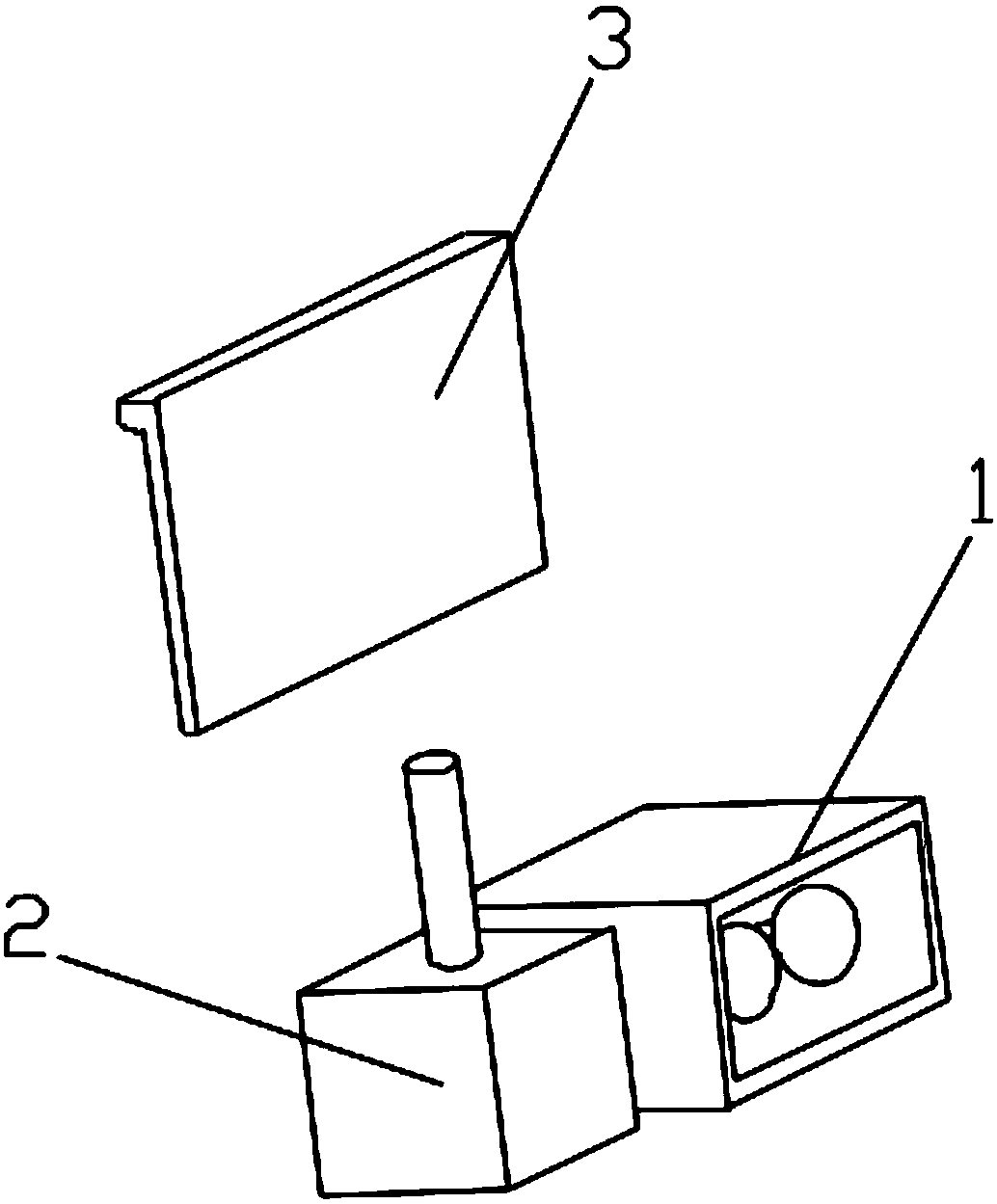
[0042] Such as Figure 1-5 As shown in , a space-time coupling control method for a lighting system capable of canceling interference, its equipment consists of a light source module 1 that can be quickly turned on and off, and a light filter module 3 that can quickly switch between transparent and opaque screens . A system control module 2 that performs state control of the light source module and the light filter module, the light source module 1 is connected to the system control module 2 , and the light filter module 3 is connected to the system control module 2 .

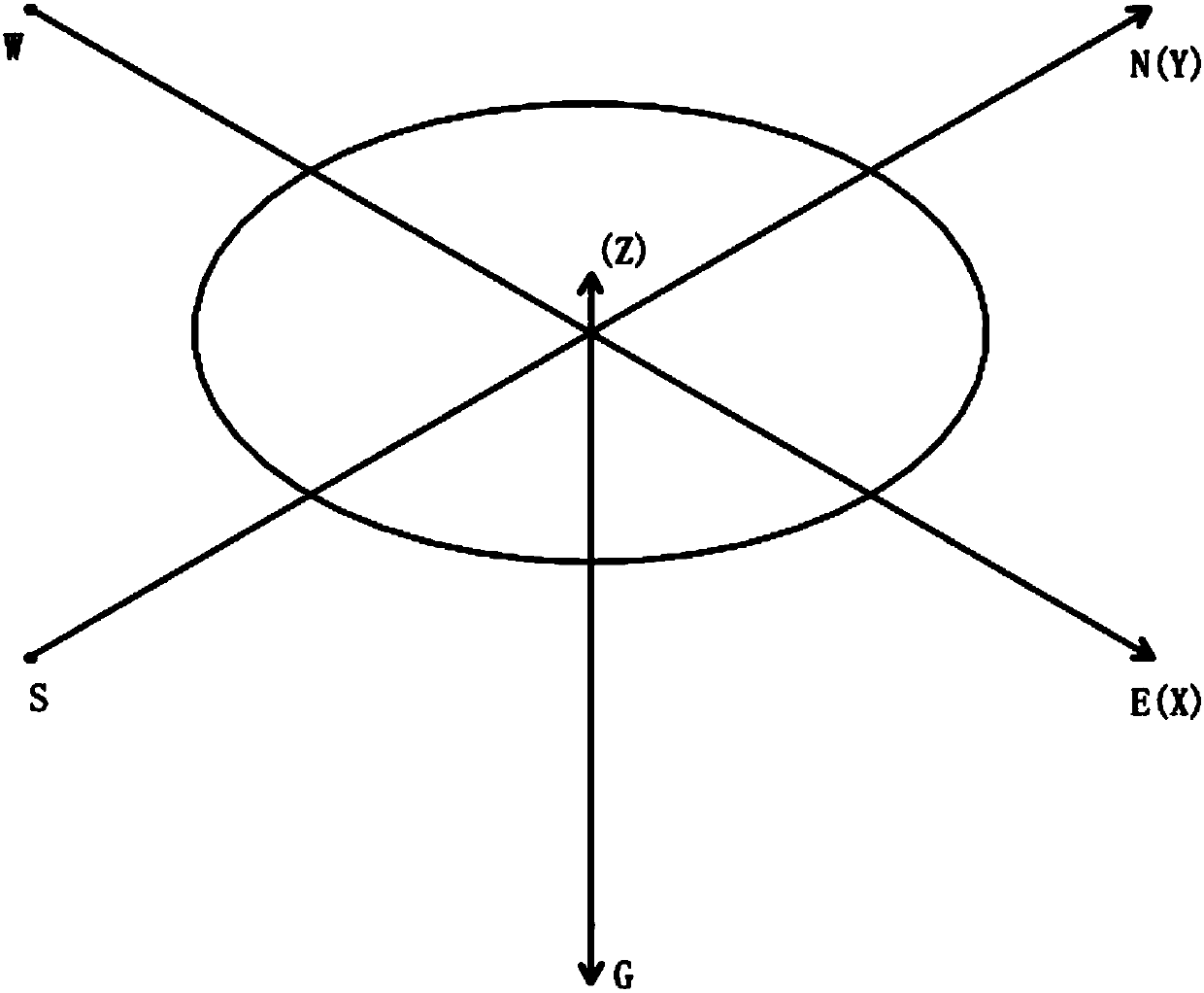
[0043] The method is as follows: correspond the start time of the period to the angle 0 degree of the working reference surface corrected by the angle offset; The direction is the same, such a period of time corresponds to the angle of the working reference plane for one week, and makes the angle value and the period time form the following mapping relationship: Where D' is the angle, M' is the moment, and T'...

Embodiment

[0071] Assume the preset parameters are:

[0072] T=1 second, L=90 degrees, V=120 degrees, S=90 degrees.

[0073] D value variation range (0≤D0 ≤Mmax ) where T=1, then the variation range of M is (0≤M<1).

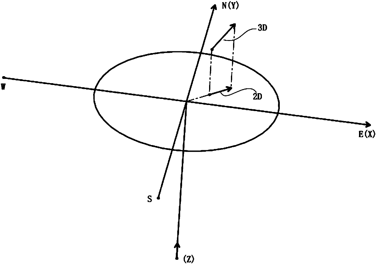
[0074] When the D value is 90 (the projection of the irradiation direction of the light source on the reference plane is northward), and the E value is 270 (the projection of the irradiation direction of the interference light source on the reference plane is southward):

[0075] Substitute into the above formulas Ls, Le, Vs, Ve respectively, the values ​​are:

[0076]

[0077] When M=0.875, the light source lighting operation is performed.

[0078]

[0079] When M=0.125, the light source is turned off.

[0080]

[0081] When M=0.3333, set the light filter to be opaque.

[0082]

[0083] When M=0.6667, set the light filter to be transparent.

[0084] When D and E change, such as D=180 (the projection of the light source’s irradiation direction on the refere...


PUM


Abstract

The invention discloses a space and time coupling control method with a mutual interference elimination function for lighting systems. The space and time coupling control method has the advantages that principles of persistence of vision of human eyes are applied, stroboscopic light sources with the frequencies higher than perception frequencies of the human eyes are utilized, light sources are periodically in luminance and non-luminance states, light ray filters are in shielded and unshielded states, accordingly, the light ray filters are in the shielded states if the light ray filters of oneof every two corresponding facilities are exactly in transparent states when the light sources of the other facility with light ray interference with the first facility are illuminated, the light sources of the other facility are in extinguished state, states of every two corresponding facilities are alternately switched, light rays emitted by the light sources of the first facility still can beseen while interference light rays of the other facility are filtered, and objects irradiated by the light sources of the first facility can be clearly seen; the redundant and harmful light ray interference can be eliminated under the condition of inevitable light ray perpendicular incidence by the aid of the space and time coupling control method with the mutual interference elimination functionfor the lighting systems.

Description

technical field [0001] The invention belongs to a space and time coupling control method of a lighting system capable of canceling interference. Background technique [0002] It is difficult to leave the lights in people's daily life, such as: traffic needs high beams for lighting, engineering needs construction operations, tunnels need to work in mines, so at night, people often have difficulty avoiding direct light, and light Disturbances have varying degrees of impact on production and life. Contents of the invention [0003] The object of the present invention is to provide a space and time coupling control method of a lighting system that can eliminate redundant and harmful light interference and can cancel interference in the case of unavoidable direct light. The method describes the control logic and generation time Calculation method of control points. [0004] In order to solve the problems of the technologies described above, the technical solution of the prese...

Claims


Application Information

Patent Timeline
IPC IPC(8): G06F17/50H05B37/02
CPCG06F30/20H05B47/10Y02B20/40
Inventor 陈兴华
Owner 陈兴华
Why Eureka
Try Eureka